I started this page for distributing information about the balancer electronics that had been ordered in different configurations already about 40 times.
Sorry, no more PCBs available!
Ill leave this page up as a reference for interested homebuilders. A new, modified drawing of the balancer mechanics is available, as well as some drawings of the main mechanical components with dimensions (...finally). Click here for download (418k)!
Currently Im considering a more sophisticated balancer electronics but this will still take much time. No more than a few vague ideas for now.
Here is a picture of the assembled Trigger/Motor Controller/Power Supply Board with some descriptions:
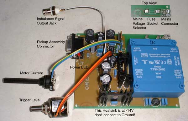 |
The mains voltage will be preconfigured to the specified value but can easily be changed afterwards by soldering of two wire jumpers. The size of the PCB is approximately 100*124mm², total height of 30mm, with the DSub 9F connector projecting from one side about 5mm (measured to mounting flange). A suitable cabinet will need to be supplied by the builder. The two long sides of the PCB are kept free of copper traces and components so a typical Euro-size PCB (160*100mm²) cabinet with slots to slide in the PCB will be suitable. As well four mounting holes are drilled at the edges of the PCB to mount it conventionally on isolating posts. The BNC Imbalance Signal Output Jack is supplied but wont be required to perform balancing, so it might be mounted or left away according to the preferance of the individual builder. The knobs to mount on the shafts of the two pots will also need to be supplied by the builder (shaft diameters 6mm and 6.35mm - 1/4) as well as the mains cord and switch.
As the duty cycle of the motor controller can be varied between approx. 5% and 95% the motor wont come to a complete stop if not loaded, but thats no problem anymore as soon as the motor pulley is linked to the shaft of the wheel to be balanced via a belt.
The power LED may be bent to be located in a hole in the front cover of the cabinet.
When mounting the PCB be sure to place an isolating foil or plate below it as to prevent it from touching the metal base of the cabinet, resulting in short circuits and possibly damage to the electronics or danger to the builder. Be sure to have the cabinet (if made of metal) properly earthed. If you are not familiar with electrics or electronics and dont exactly know how to connect the PCB to the mains you might better ask somebody who knows as it can be extremely dangerous if the mains is connected in the wrong way.
This is a picture of the assembled buffer PCB, two of which are required for the balancer.
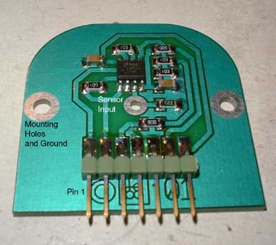 As all the components are SMD
(surface mounted devices) the buffer PCB can be mounted directly onto the piezo disk retainer. The size of this PCB is just 38*38mm². It is advisable to use a spring assembly to contact the signal face of the piezo disk as
the piezoelectric material deteriorates rapidly when heat is applied (by soldering). The ground signal will be connected through the mounting screws.
As all the components are SMD
(surface mounted devices) the buffer PCB can be mounted directly onto the piezo disk retainer. The size of this PCB is just 38*38mm². It is advisable to use a spring assembly to contact the signal face of the piezo disk as
the piezoelectric material deteriorates rapidly when heat is applied (by soldering). The ground signal will be connected through the mounting screws.
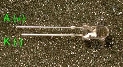 This picture shows the white LED and
its polarity. If the terminals are connected in reverse the LED wont be damaged but it wont light either.
This picture shows the white LED and
its polarity. If the terminals are connected in reverse the LED wont be damaged but it wont light either.
How does the Balancer work?
Each rotating mass will cause a centrifugal force, pointing away from its rotational axis. In the ideal case that every mass segment is countered by an equal mass on the other side of the rotational axis, there will be no resulting force (except gravitation) that needs to be carried by the shaft or the bearings during steady rotation.
But due to manufacturing tolerances or uneven distribution of alloy components during casting, all rotating components will reveal a more or less severe degree of imbalance. This will cause a vibrating force exerted to the bearings of the rotor and hence can be measured by force- or translation-transducers attached to the bearings.
As a typical translation-transducer a magnetic transducer will require significant movement to generate a reasonable output voltage, thus demanding for a soft suspension with the accompanying low resonant frequency, well in the range of rotational speeds. So I didnt choose one of these in my balancer design.
A piezoelectric transducer measures force and is a very stiff device, and by arranging two in a push-pull arrangement the elastic constant will still be increased. The problem is that these transducers can be considered from the electrical point of view as a variable voltage source (depending on the applied force) in series with a capacitor (depending on the material properties and the size). In conjunction with the following high-impedance buffer's input resistance this will form a high-pass filter with a characteristic time constant (T=R*C). Only if the period of the rotational frequency is well above this time constant the output signal will be in phase with the force applied to the transducers. But the time constant achievable in my balancing setup will be around 1s, thus all balancing RPMs above about 500/min will be fine.
The other reason I went for the piezos is that they are cheap. They originate from sound transducers (well, actually beepers ;-) and cost the equivalent of approx. 50US cents.
Now arises the question: How is the position and amount of imbalance to be determined?
This purpose serves a trigger circuitry with a variable level. It is a simple voltage comparator, driving a constant current source as LED driver. The inverting input of the comparator is connected to a variable voltage source while the noninverting is fed with the output of the transducer/buffer assembly.
If this "imbalance signal" increases above the trigger level momentarily the LED will be lit.
The trigger level will then be set to a value that only the most positive part of the imbalance waveform will exceed the trigger level. If the LED is pointed to the wheel to be balanced, this seems to be standing still (stroboscopic effect). If there has been a mark placed on it before (or has already been present), you can stop the wheel and place it statically in the position that has been spotted with the LED.
In this position the "heavy side" of the wheel will point directly to the transducer that causes the LED to light when pushed on (the "+" transducer).
Now a counterweight will be attached to the other side of the wheel (usually I use textile adhesive tape) and the balance re-checked. During this process the trigger level will have to be set lower each time, as the imbalance decreases. When the vibration caused by imbalance approaches the noise level generated by the bearings, it becomes difficult to find a trigger level setting that will give a "standing" wheel display, then I usually stop and grind some material off the wheel at the side opposite from the counterweight. After that I remove all the tape and start over again to check if I took the right amount of material off.
This method requires some experience but it is possible to detect a difference with a piece of tape the size of 1mm², depending on the condition of the bearing surfaces of the shaft. And you'll get balancing finished in a reasonable time compared to other homebrew methods.