BLMC or BrushLess Motor Controller
The reputation for this project doesnt belong to me but to Bernhard Konze, with whom I met by means of his web site (and -unfortunately- not even know in person). He designed a small brushless motor controller, intended for small model aircraft and and meant to be constructable by modellers with some electronic assembly skills, at very low expense (15-20 Euro). In order to be able to do so, Bernhard offers the schematic as well as the firmware for the controller on his web site for (free) download. All that had been missing was a suitable, compact PCB design.
In search for an option to design a brushless motor controller to drive a starter/generator for a small gas turbine engine (still 150...200 shaft horse power), and after one failed attempt using a Toshiba TB6537 (well, well, better dont even try this in the first place...), I somehow found Bernhards web site.
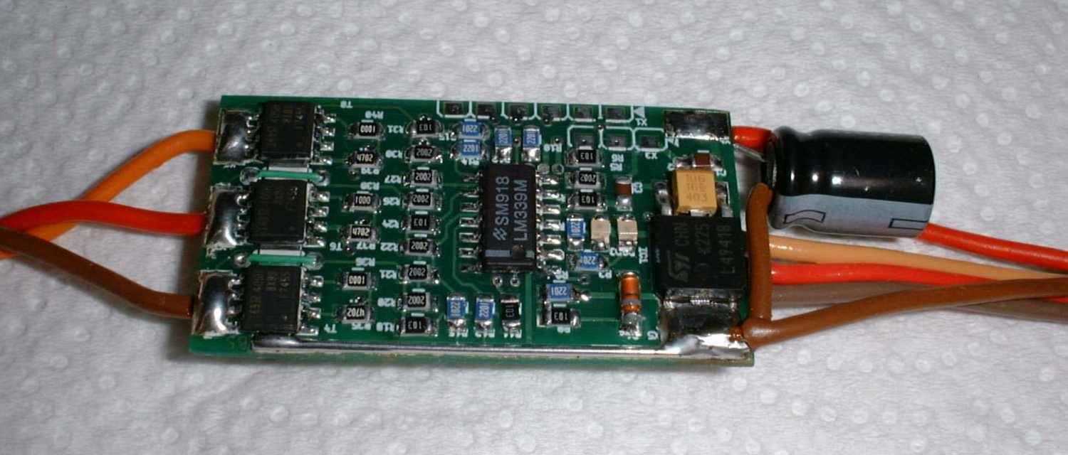
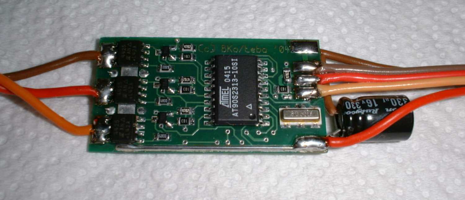
This project and Bernhards selflessness amazed me so much that I immidiately offered to contribute to it. About a week later, a very nice, small PCB layout was finished on my PC, and a hundred pieces of the PCB had been ordered. Two more weeks passed and the PCBs arrived and I already had the first two BLMCs assembled that evening.
 |
 |
The very next day, Bernhard received his assembled PCB, and to my great joy, his controller worked immediately after uploading the firmware.
Currently, Bernhard is still doing a little tweaking of some parameters regarding the current limiting routine and the timing, but basically the controller is already usable with the current software revision. At an assembled weight of 4g (less cables), the BLMC is very well suited for modeified CDROM spindle motors with current consumptions of up to 5A (maybe more one day...).
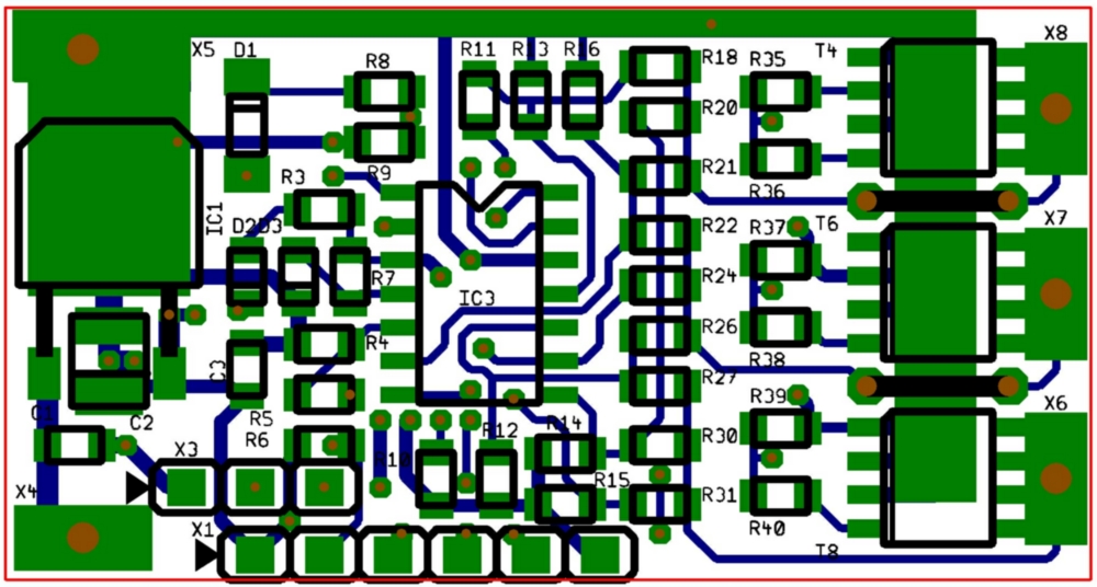
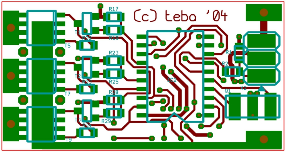
If you fellow model makers now feel an itching in the fingers and a strong urge to build such a device yourself, you may download the PCB layout in Target 3001!-file format as well as the place plans of assembly- and solder sides and the bill of material here:
New: As a reaction to inquiries of several fellow BLMC homebuilders, I made this PDF available (308kB) that simplifies the assembly by arranging the bill of material and placeplan per layer. I suggest to print out the file and use a pencil to check all the parts already assembled.
New: Roman Gargulak from Canada was so kind to prepare a version of the BOM with Digikey part numbers/order codes and gave me permission to publish it on my BLMC page. This may help BLMC homebuiders from the American continent to finish this project since Digikey seems to be one of the big electronic components distributors there. Heres the file in Excel spreadsheet format (XLS, 69kB) . Thanks, Roman!
Since a PCB like this isnt easily home-made in the shed, Ill offer the surplus, professionally manufactured ones for sale. The dimensions of the PCBs are 40 x 22mm² and 0.8mm thick. If you are interested, please mail me at Contact.
Attention: PCBs are sold out again... But I plan to offer an improved version one day in future (with the ATMEGA 8 as controller).
Here are a few hints regarding assembly. I gave them similarly to Bernahrd as well:
Instead of the SI4420, you can also use the IRF7455. Nessel Elektronik (quite inexpensive german supplier for the power semiconductors) sent those as a replacement for the (as they said) obsolete 4420. The components are already pretty small so that assembly takes a while. Especially the 806 LEDs are a pain in the ass ;-) since there isnt a marking of anode or cathode - or at least I didnt find one. So a multimeter in diode test mode is used to figure out which way round the LEDs will glow. As the diode for the current limiting circuitry, I considered both schottky (BAS85, grey ring) and conventional (BAV103, green ring). Time and experience will tell which diode is better suited and offers best protection for the circuit. Update: Use the BAV103 or another PN diode like the LL4148 or similar. I used 330µF electrolytics instead of the 47µF as the power supply buffer cap since I just had them handy as low-ESR (Rubycon ZL) versions. They are to be soldered to the power supply pads of the BLMC externally.
During assembly it is important to mount the 10µF tantalum electrolytics before the voltage regulator. The latter restricts access to one fo the terminals of the electrolytics (which looney designed this crappy PCB??...;-). Also it is a good idea to check for shorts between the terminals of this electrolytics since beneath it, theres a via very close to one of its pads (just check for continuity between its two terminals with an ohm meter - there should be none!). The copper tracks to the power stage arent covered by the silkscreen mask since copper wires will be soldered to them at the whole length to allow them to handle the relatively high currents. During this task, special care has to be taken at the line carrying positive battery voltage in order to prevent shorts to the vias in its proximity. If any one exists, the Atmel will be killed immediately. The SMD ceramics resonator is mounted most easily if initially no solder at all is placed on the pads. After the resonator is aligned, only very little amounts of solder are applied at both sides to all three terminals.
Dont forget the two wire jumpers between the MOSFETs -- without them, the EMK feedback wont work.
Now heres one more hint to avoid diasappointment: The whole BLMC is designed form very small components, mostly SMD size 805. If you have no idea what this means, you should rather refuse to build one. At least this controller isnt a project for beginners in SMD assembly. As well, I wont supply any pre-programmed microcontroller chips or other components for this project except for the bare PCB. There are a lot of public designs of programmers for Atmel microcontrollers available on the web, have a look here for instance. So please check the web before mailing me questions concerning this issue (sorry, Im receiving about 20 mails a day regarding my gas turbine sites...). And please dont get impatient if my reply takes a while - this isnt meant as an offence, its just that I have to do work to pay bills now and then. If in doubt, please simply re-send your inquiry.
After all this nonsense, heres the link to Bernhards site once again. Bernhard and me decided to keep the software stuff on his site while the PCB design is located on mine. This way each of us keeps control over the things he does best :-).
http://home.versanet.de/~b-konze/blmc_bko/blmc.htm
Last but not least the usual disclaimer on responsibility...
Neither Bernhard nor me will accept any resposibility for potential damage or injury that might result form building the device(s) described on our sites, respectively. Every person who builds this device is legally considered the manufacturer and will be held responsible him- or herself for any claims. Moreover, a commercial use of the information distributed herein is only permitted with the written consent of both of us. Any rights of third parties are to be checked for by the potential manufacturer.