Turbocharger Gas Turbine Engine

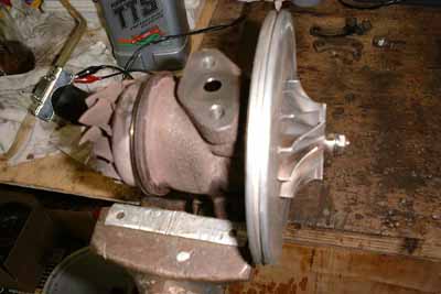
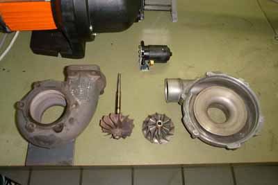
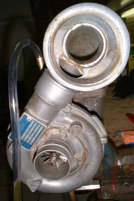
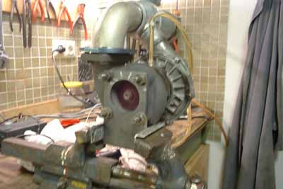
One day, I think it must have been about december 1999, a friend of mine mentioned in a subordinate clause, that he has still an old turbocharger sitting on his shelf, remaining from his former life as a car mechanic. He asked if I could think of anything to do with it. I smiled and said “Of course I do!” So he donated it to me. Thanks, Peter!

The turbo is a KKK brand (nowadays 3K Warner) and was taken out of an Audi 5T due to loss of power. First I disassembled the turbo completely to diagnose the cause of the failure. I won’t have believed that there could be so much dirt in one little turbocharger. My fingernails showed traces of black for about one week...

The main problems were large amounts of oil carbon deposits in the whole hot section, and also some debris in the small oil ducts to the hydrodynamic bearings. Otherwise the turbo seemed to be in a very reasonable condition. Even the bearings seemed to be ok.

The turbo was probably used with the wrong oil or the oil filter broke down.

The core of the turbo, after cleaning and reassembly. The wheels are 66mm in diameter, the vane tip height of the compressor is approx. 7mm. The bearing housing features oil-lubrication and -cooling. So after shutdown of the turbine there should be some air forced through the turbo to allow cooling.

Snailshell housings of the compressor and the turbine, the disassembled rotor and a small gearpump I use for lubrication.

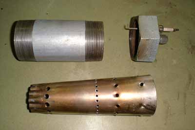
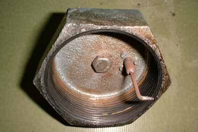
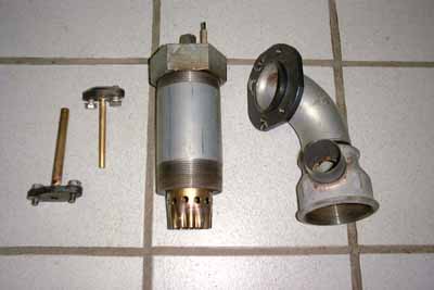
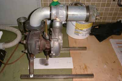
So I started thinking about how to design and build a combustion chamber as simple and cheap as possible. I decided to use steel water fittings for the main components and build some kind of reverse-flow combustor. For the first experiments I planned to use gaseous propane as fuel, which is very easy to ignite and has a wide range of combustible mixture ratios with air. On the other hand it forms easily explosive mixtures with air, should it leak somewhere out of the engine.

These are the components of my combustion chamber. The outer shroud is a 21/2” steel tube with threads on both sides, total length 150mm. The flame tube is of a conical shape with air holes drilled in circles around the circumference. This picture shows the hole arrangement I used for the first experiments. The hot gas discharge orifice of the flame tube is folded twelve times around the circumference to allow it to stick into the turbine inlet manifold and to supply some compressor delivery air to the manifold walls for cooling.

The combustion chamber cover contains the propane nozzle, which is made out of an M8 hex head screw. The head is drilled through in all three directions (1mm dia), thus forming six orifices. The shaft of the screw is then drilled (3mm dia) down to the point where the small holes cross.

This picture shows the view through the compressor air distributor into the turbine inlet manifold. These two components required most of the work on the whole engine so far. The turbine inlet manifold is made out of a 2” 90° steel elbow fitting, one inner and one outer thread. The inner thread side has been turned down to form a conical section, so that it can be bolted to the turbine inlet port via a retaining plate made of 8mm steel plate. The inner diameter of the manifold matches the diameter of the turbine inlet port.

The compressor air distributor consists of a 21/2”-2” reduction fitting with inner threads, as for the manifold to fit into the smaller and the combustion chamber shroud into the larger orifice. A big hole is milled into the side to match the compressor housing discharge port. A conical steel tubing segment is hard-soldered into this orifice. The conical section of this tube fits closely into the compressor discharge port.

These are the main components needed to make a gas turbine engine out of a turbocharger. On the left are the oil fittings that bolt directly to the turbo main casing, in the center the assembled combustion chamber with the flame tube sticking out of it, and on the right the turbine manifold with retaining plate and compressor air distributor.

The first experiments lighting the combustion chamber with a torch behind the turbine outlet proved to be quite difficult, if not dangerous.

So a high.tension ignition system derived from an old oil furnace burner was added. One of the ignitor electrodes was mounted to the combustion chamber cover. The flame tube wall forms the ground electrode. The high voltage transformer was also taken from the oil burner. It produces a really hot spark, the whole tip of the electrode is glowing orange.

Ok, so we are ready to run the baby for the first time. I modified an old vacuum cleaner to provide the air for starting. An empty gherkin glass made a nice oil tank, containing about half a litre synthetic castrol two-stroke oil. I chose this oil because it should barely leave any deposits when heated or burned. A small filter was added to the oil pump intake. After activating the oil pump and the vacuum the turbo began to spin up, but it didn’t go nearly as fast as I expected. I nevertheless switched on the ignition and opened gradually the propane valve (though I was a little scared about what would happen). The gas ignited immediately and the turbo accelerated quickly. Once the combustor is burning I can switch off the ignition, it never flamed out. When the oil is about 50°C I can get the engine to self-sustain with a short burst of gas. I believe my vacuum is a little weak for starting the turbo. I measured the EGT just a few rpm above self-sustain at 570°C. My propane bottle is equipped with a variable pressure limiter and I have set it to minimum. Currently I haven’t got a pressure gauge fitted.

Wow, what a blast. This was the first time I took my hand off the fuel valve with the engine running, just to photograph the turbine outlet. The CCD in the digital camera seems to be a little more sensitive to near infrared light than the human eye (at least as my eye). I didn’t see the turbine wheel glow at all. The turbine glows only when it is accelerated from “vacuum speed” to somwhere above self-sustain.

Finally I managed to weld a simple turbine stand to start the engine outside the workshop. This is one of the conditions to be able to run the engine at higher power levels. I will also add an oil tank, -pump and -cooler and some basic instrumentation. Maybe I can add a nozzle in the turbine casing to start the engine with pressurized air. I’ll also have to include an RPM pickup into the compressor housing. Work is proceeding slowly, but...

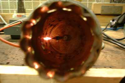
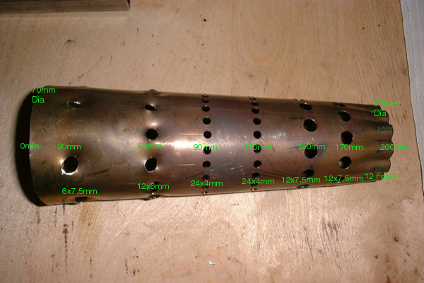
And now for the good stuff: The hole pattern of my optimized flame tube. I have made some comparative calculations on the relation of flame tube hole area and compressor wheel discharge (circumferential) area. I used some drawings of well-proven model aircraft gas turbine engines for comparison, that use very similar compressor wheels. This led to an increase of hole size and count in my flame tube. The hole balance between primary and secondary zone, though, had to be maintained. The primary zone holes are tweaked to induce swirl in this area. The engine runs very smoothly with this tube and EGT still decreased a little. The tube is rolled out of 1mm V4A sheet metal (316 or 318 stainless). A friend of mine welded the joint for me. And this is my flame tube:


April 2001

I gave this turbine to Nicolas Benezan (Bene). He is going to do further experiments and add some instrumentation to this engine. Have a look at his page

http://www.nicolas.benezan.de/Gasturbines/Turbocharger.html

for further information. I simply have too many hobby projects at a time and Bene is preparing to build a larger engine. So this one will be a perfect device for getting familiar with a turbine and for testing some data acquisition equipment.

Have LOTS of fun, Bene!