Calculation of the gearbox ratio
After several inquiries concerning the calculation of the gearbox transmission ratio I decided to set up this page. I tried to keep the mathematics minimal but we wont get around without. So heres a schematic of a differential planetary gear. For simplicity only one planetary gear of each layer is shown. As well only the the intermeshing lines of the gears are shown as thats all that is required for the calculation. Since the modulus of the gears is usually the same for every member of this gearbox (though they might differ in the different layers), I base explanation on the circumferences, angles and radii or diameters. The gears belonging to the same layer are drawn in the same colour.
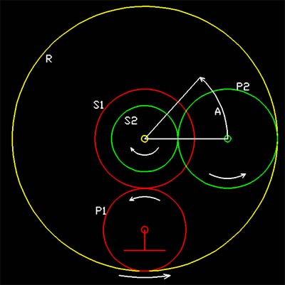 The sun gears of both layers, S1 and
S2 are splined together and thus rotate at the same speed. The planetary gears of the first layer, P1, are assumed to be suspended on the casing, hence their centre is fixed and they are only allowed to rotate around
this centre. In contrary to this the panetary gears of the secondary layer, P2, are suspended on a spider so they will be able to rotate around their centre, and this centre will be able to rotate round the centre of the sun
gears. The spider is usually attached to the output shaft. The ring gear R is common to both layers and is allowed to rotate freely. In case of the TS-21 gearbox there even isnt a dedicated
suspension for this ring gear, only a recess inside the toothing of thr ring that is located between the two layers keeps it in place.
The sun gears of both layers, S1 and
S2 are splined together and thus rotate at the same speed. The planetary gears of the first layer, P1, are assumed to be suspended on the casing, hence their centre is fixed and they are only allowed to rotate around
this centre. In contrary to this the panetary gears of the secondary layer, P2, are suspended on a spider so they will be able to rotate around their centre, and this centre will be able to rotate round the centre of the sun
gears. The spider is usually attached to the output shaft. The ring gear R is common to both layers and is allowed to rotate freely. In case of the TS-21 gearbox there even isnt a dedicated
suspension for this ring gear, only a recess inside the toothing of thr ring that is located between the two layers keeps it in place.
Now lets assume the drive shaft, connected to both sun gears, rotates one complete turn in clockwise direction. This will cause the ring gear to turn the circumference of the first sun gear in counterclockwis direction. Circumferential advance of the ring gear at the intermeshing line will be dUR = - pi * DS1 = -US1. D means diameter of the referring gear, U the circumference, dU a partial circumference and pi is the circle constant 3.1415... The minus sign is due to the fact that the ring gear rotates in the opposite direction of the sun gears. At the same time the circumferential advance of the second sun gear S2 is simply its circumference, namely US2 = pi * DS2.
Now the question is, how far will the secondary planetary gear travel under these controversing motions. As a first step to consider this it is easier to imagine this motion to take place in a linear dimension, i.e. to assume that the intermeshing surfaces of R and S2 are developed into linear gears, moving at the same linear velocity. Then it becomes quite obvious that the centre of P2 will move at the mean velocity of both S2 and R, hence dUP2,C = 1/2 * (dUR + US2), where the index P2,C means the motion of the centre of P2. To convert this linar motion into an angular one, only the radius the centre of P2 describes, needs to be known. This radius is exactly the mean radius of S2 and R: rP2,C = 1/4 * (DR + DS2). The factor 1/4 originates from the 1/2 of the conversion of diameter to radius times the 1/2 of the averaging between both radii. Now the angle (radial) that the centre of P2 travels is easily calculated as dA = dUP2,C / rP2,C. The gear transmission ratio is defined as n = angular motion at output / angular motion at input. Since we rotated the input shaft one complete turn, this angle is 2 * pi. Now we only need to fill in the factors from above and will get the transmission formula. The terms of the formulas are painted to indicate their origin.
n = dA / dS
n = [ dUP2,C / rP2,C ] / [2*pi]
n = [1/2*(dUR+US2) / {(1/4)*(DR+DS2)}] / [2*pi]
Now we substitute D = U / pi for DR and DS2, and dUR as above:
n = [1/2*(-US1+US2)/{1/(4*pi)*(UR+US2)}]/[2*pi]
This can be simplified as follows:
n = [2*pi*(US2-US1)/(UR+US2)] / [2*pi] = (US2-US1)/(US2+UR)
Since the circumference U is proportional to the tooth count N of the gears, The transmission ratio equals:
n = (NS2-NS1)/(NS2+NR)
If we now insert the actual tooth counts of the TS-21 gearbox, namely NS1 = 23; NS2 = 15; NR = 99, then the transmission ratio calculates as n = -0.070175... which equals a ratio of 1:14.25, the minus indicates that the output shaft is counterrotating to the input shaft.
And finally, in contrary to all the grey theory, here is a short video clip of the actual gear in rotation:
GEAR.AVI (636kB), you will need the DivX Codec to view it.
Actually the upper three planet gears are rotating on fixed bearings while the lower planet gears are mounted on the output drive shaft.