Sophia Precision J-450
Recently I managed to obtain a damaged Sophia J-450 Model aircraft gas turbine engine. I had been told the reason for failure was a disintegrated bearing, so I was prepared what I would have to expect. On the other hand I still have got a rotor out of a scrapped Garrett T3 turbocharger, that is exactly the one that is used in the J-450.
I definitely intend to rebuild the engine, because it is an incredible fine piece of mechanical engineering. Not a single KJ-66 derivative engine reaches this state of perfection. Or has anyone ever seen a carbon seal inside a model aircraft engine?
The main difference of the J-450 to most of the other model gas turbines is, that it incorporates high-pressure fuel injection and no vaporizer tubes like most of the others. It doesnt even require propane to start the engine.
This information might be of some interest for those who want to modify a JPX 240, which is basically the same design but runs on propane only. But unfortunately this modification doesnt seem to be too easy because one of the most complicated parts (shaft tunnel) will have to be re-manufactured or perhaps modified (I dont know what the shaft tunnel on the JPX240 looks like).
And now some more pictures out of my Hall of Horror and some fine details, and possibly some failure analysis.
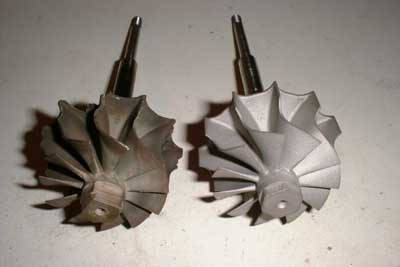
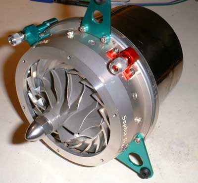
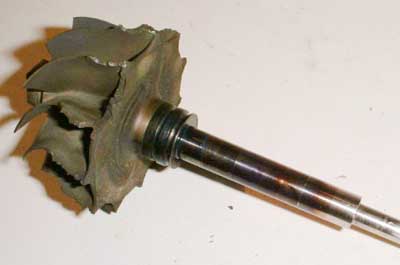 Wow, what a fine blown turbine wheel
;-). Scraps of metal are ripped out of it and all the vane-tips are thrown. The large metal face near the shaft revealed cracks all over. The previous owner must have been really lucky that the wheel didnt explode like a bomb.
The shaft is discolored almost up to the front bearing. I have never seen something like this on a wheel taken from a turbocharger. I guess the whole turbine wheel was glowing bright orange when this happened. To fit my
T3 wheel into this engine Ill just have to grind the shaft from 4/10 (10,16mm) to 10 mm.
Wow, what a fine blown turbine wheel
;-). Scraps of metal are ripped out of it and all the vane-tips are thrown. The large metal face near the shaft revealed cracks all over. The previous owner must have been really lucky that the wheel didnt explode like a bomb.
The shaft is discolored almost up to the front bearing. I have never seen something like this on a wheel taken from a turbocharger. I guess the whole turbine wheel was glowing bright orange when this happened. To fit my
T3 wheel into this engine Ill just have to grind the shaft from 4/10 (10,16mm) to 10 mm.
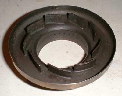
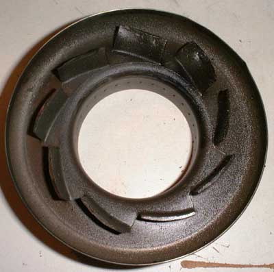 Look what the scrapnels from the
turbine wheel have done to the radial NGV! Almost all of the vanes are bent to the outside (more or less), some are warped badly and the 12 and 1oclock vanes even show signs of impact damage. And this part is
made from some tough material you bet!
Look what the scrapnels from the
turbine wheel have done to the radial NGV! Almost all of the vanes are bent to the outside (more or less), some are warped badly and the 12 and 1oclock vanes even show signs of impact damage. And this part is
made from some tough material you bet!
Meanwhile I tried straightening the vanes with partial success, but Ill rather figure out the price of a new spare before I decide to use the repaired NGV.
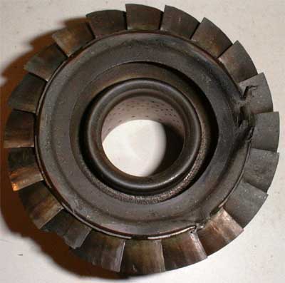 This is the inner coumbustor liner with
the integral axial NGV. The heat shield to the turbine wheel shows impact damage in two places. And some other peculiarities can be observed, namely that some of the vanes are burned badly (especially in
the 7oclock position) and some others are still shiny. This leads to the assumption that some of the injection nozzles are clogged so that the combustion pattern is extremely uneven. If then the single
thermocouple which reports the EGT to the ECU is located in one of the colder areas, well, you can guess what happens.This is one of the reasons that all of the full-size gas turbines have multiple thermocouples.
I thought of having welded some material to the damaged places and then grind it to shape again, but probably a spare would be a better choice.
This is the inner coumbustor liner with
the integral axial NGV. The heat shield to the turbine wheel shows impact damage in two places. And some other peculiarities can be observed, namely that some of the vanes are burned badly (especially in
the 7oclock position) and some others are still shiny. This leads to the assumption that some of the injection nozzles are clogged so that the combustion pattern is extremely uneven. If then the single
thermocouple which reports the EGT to the ECU is located in one of the colder areas, well, you can guess what happens.This is one of the reasons that all of the full-size gas turbines have multiple thermocouples.
I thought of having welded some material to the damaged places and then grind it to shape again, but probably a spare would be a better choice.
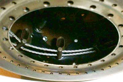
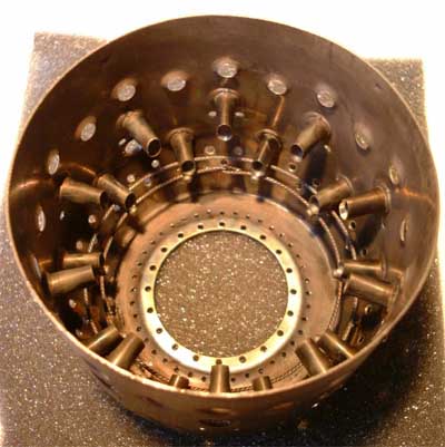
 This is the outer combustor liner.
There is only minor damage to this component that is barely visible in this picture and can easily be rectified by slight hammering and sanding. One difference between this combustor and the one of the JPX 240 are the
two flame holder fences (concentric trifilar twisted wire rings out of 0.6mm, probably stainless) near the bottom. Parts of these rings are missing and might have caused foreign object damage (FOD) to the turbine wheel.
These rings will have to be replaced. The small tubes projecting radially into the combustion chamber are air nozzles that meter the combustion air into the primary zone.
This is the outer combustor liner.
There is only minor damage to this component that is barely visible in this picture and can easily be rectified by slight hammering and sanding. One difference between this combustor and the one of the JPX 240 are the
two flame holder fences (concentric trifilar twisted wire rings out of 0.6mm, probably stainless) near the bottom. Parts of these rings are missing and might have caused foreign object damage (FOD) to the turbine wheel.
These rings will have to be replaced. The small tubes projecting radially into the combustion chamber are air nozzles that meter the combustion air into the primary zone.
 Here the flame holder fences can be
seen more clearly. The supporting studs seem to be spot welded to the front primary air nozzles. Each one has two holes through which the wire runs. Currently I have removed the wire completely and will try to replace
it with 0.6mm stainless MIG welding wire. The original wire was surprisingly brittle. It also reveals to be magnetic, so I doubt it was stainless. Possibly a too weak material on this 50cents-part has caused the whole
engine to fail?
Here the flame holder fences can be
seen more clearly. The supporting studs seem to be spot welded to the front primary air nozzles. Each one has two holes through which the wire runs. Currently I have removed the wire completely and will try to replace
it with 0.6mm stainless MIG welding wire. The original wire was surprisingly brittle. It also reveals to be magnetic, so I doubt it was stainless. Possibly a too weak material on this 50cents-part has caused the whole
engine to fail?
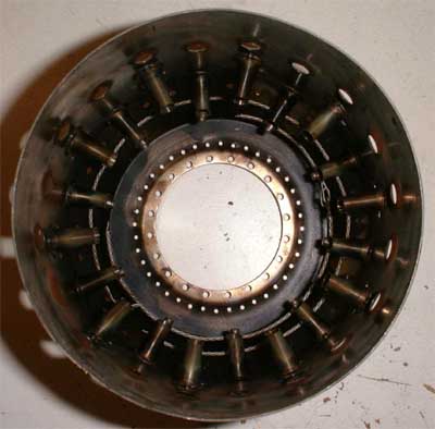
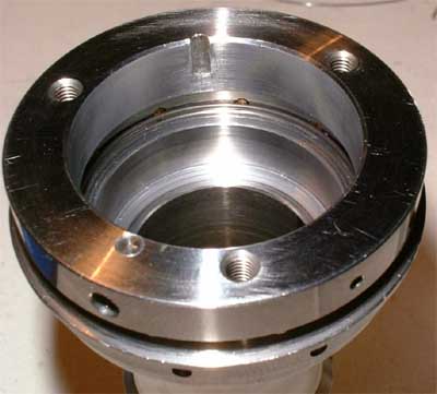
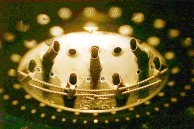
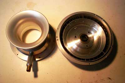
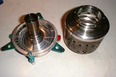
 In this picture the fuel- and oil feed
pipes projecting through the compressor diffusor into the front of the bearing tunnel can be seen. The many holes in the bearing tunnel supply compressor delivery air to the inside of the combustor. Just below
the fuel nozzle ring is visible (slightly covered by brownish dirt).
In this picture the fuel- and oil feed
pipes projecting through the compressor diffusor into the front of the bearing tunnel can be seen. The many holes in the bearing tunnel supply compressor delivery air to the inside of the combustor. Just below
the fuel nozzle ring is visible (slightly covered by brownish dirt).
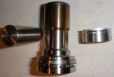 This is the shaft tunnel, the front
bearing retainer (right) and a front bearing removal tool (left) I had to make to extract the bearing. The shaft tunnel is an increadibly fine piece of machining work, besides containing the two hybrid angular contact
bearings it does the oil-air mixing, supplies air through 20 axial holes to the inner combustor liner, accepts the rear bearing preload spring and contains ten fuel injection nozzles as well as all the fuel distribution ducts.
This is the shaft tunnel, the front
bearing retainer (right) and a front bearing removal tool (left) I had to make to extract the bearing. The shaft tunnel is an increadibly fine piece of machining work, besides containing the two hybrid angular contact
bearings it does the oil-air mixing, supplies air through 20 axial holes to the inner combustor liner, accepts the rear bearing preload spring and contains ten fuel injection nozzles as well as all the fuel distribution ducts.
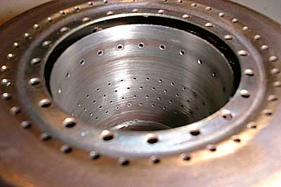
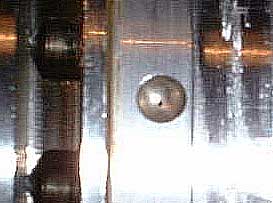 This picture shows one of the ten injection nozzles along
with two of the air passages to the inner combustor liners (compressor side). The Nozzle itself has a diameter of approx. 0.15mm. Yet I wasnt able to figure out if the nozzles are formed by a separate ring that is
shrunk onto the thaft tunnel body or if the larger portion of the nozzles have been drilled from the inside (which would have required some kind of dentists tools).
This picture shows one of the ten injection nozzles along
with two of the air passages to the inner combustor liners (compressor side). The Nozzle itself has a diameter of approx. 0.15mm. Yet I wasnt able to figure out if the nozzles are formed by a separate ring that is
shrunk onto the thaft tunnel body or if the larger portion of the nozzles have been drilled from the inside (which would have required some kind of dentists tools).
 This is a shot into the front area of the
shaft tunnel. A groove is turned into the inside to accept a steel wire ring (spring) that holds the nozzle swirl bodies (brass) in place. I cant wait to get the replacement O-rings that seal
the fuel distribution ducting and test the combustion system outside of the engine. I wonder if all of the nozzles are working or if some increadibly difficult cleaning would be required.
This is a shot into the front area of the
shaft tunnel. A groove is turned into the inside to accept a steel wire ring (spring) that holds the nozzle swirl bodies (brass) in place. I cant wait to get the replacement O-rings that seal
the fuel distribution ducting and test the combustion system outside of the engine. I wonder if all of the nozzles are working or if some increadibly difficult cleaning would be required.
Added 12/14/2000
Yesterday I spent some time in the workshop after I decided that I will do the grinding of the turbine shaft myself. I had an offer by a fellow model aircraft pilot to have the shaft ground by a friend of his, but I didnt want to bother him and on the other hand when I scrap it I know whos to blame ;-)
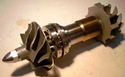
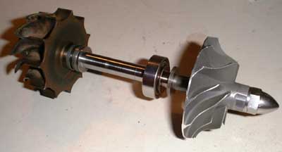 As you see I was quite lucky and
didnt scrap it. This is the whole rotor with the remaining intact bearing in place. I am very happy with the result as the fits are almost perfect, the bearing slips smoothly over the seating areas on the shaft without any
observable toggle. The concentricity is better than 1/100mm. Ill just have to figure out where I can sandblast the turbine wheel to remove the burnt-on soot, remaining from its former life in a turbocharger.
As you see I was quite lucky and
didnt scrap it. This is the whole rotor with the remaining intact bearing in place. I am very happy with the result as the fits are almost perfect, the bearing slips smoothly over the seating areas on the shaft without any
observable toggle. The concentricity is better than 1/100mm. Ill just have to figure out where I can sandblast the turbine wheel to remove the burnt-on soot, remaining from its former life in a turbocharger.
 I also straightened the vanes of this
radial NGV, but I think I will use a new one because this is one of the hottest components in the engine and I really dont want it to fail
I also straightened the vanes of this
radial NGV, but I think I will use a new one because this is one of the hottest components in the engine and I really dont want it to fail
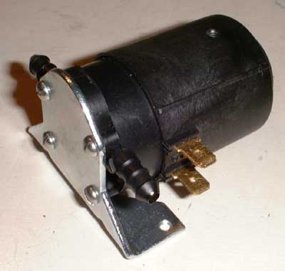 This is the small gear pump I intend to
use to pressurize the fuel. I didnt get the original pump with the engine beacause the previous owner kept it for usage in a different project. This pump is supplied by Franz Kavan and is rated at 12V. Yet Ill have to figure
out if its powerful enough to produce the required pressure.
This is the small gear pump I intend to
use to pressurize the fuel. I didnt get the original pump with the engine beacause the previous owner kept it for usage in a different project. This pump is supplied by Franz Kavan and is rated at 12V. Yet Ill have to figure
out if its powerful enough to produce the required pressure.
And now for some fine electronics and some crude patches
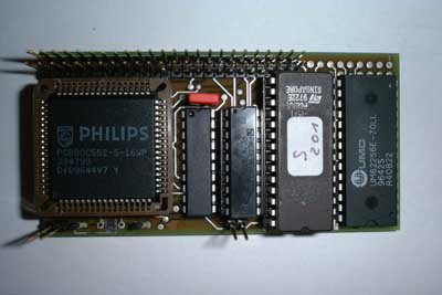 Thats the digital board of the
Jettronic UNI-1, made by CAT (yes, the guys that make the JetCat), which I got along with the engine. The controller is a Philips 80C552 and it is equipped with 64kB of Eprom and 32kB of RAM. So this microcomputer
should be more than able to make a super- sophisticated ECU.
Thats the digital board of the
Jettronic UNI-1, made by CAT (yes, the guys that make the JetCat), which I got along with the engine. The controller is a Philips 80C552 and it is equipped with 64kB of Eprom and 32kB of RAM. So this microcomputer
should be more than able to make a super- sophisticated ECU.
 As always, theres no light without
shadow. The opto-isolator board for interfacing to the R/C equipment is more than a nightmare. I wont trust my expensive model to a disaster like this. Almost all of the printed wires are scratched through and are routed
differently by the use of wire-wrap wire. This wire isnt secured, though, and the soldering on this piggyback board can only be called catastrophic!
As always, theres no light without
shadow. The opto-isolator board for interfacing to the R/C equipment is more than a nightmare. I wont trust my expensive model to a disaster like this. Almost all of the printed wires are scratched through and are routed
differently by the use of wire-wrap wire. This wire isnt secured, though, and the soldering on this piggyback board can only be called catastrophic!
I will redesign this piggyback board and replace it, so I wont have to worry about this.
I expect CAT wont deliver something like this nowadays anymore, else they wont be so successful whith their JetCat engines.
-------------------------------------------- Inserted 12/31/2000 --------------------------------------------
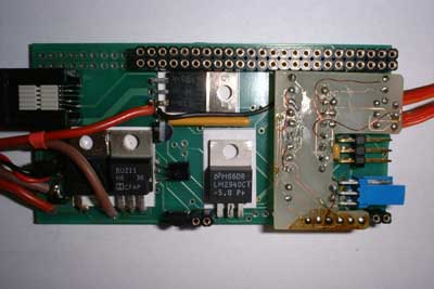
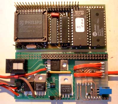 Here is a picture of the replaced
opto-isolator piggyback board to improve reliability. I placed it here for better comparison, though it doesnt match the chronological order. The board is made from 0.5mm epoxy PCB material, the residual copper is
milled away on my small CNC mill to form the copper tracks. This may not be the most economic way to make a PCB, but I like it very much because I wont need all the chemistry required for the conventional etching process.
Also the time from CAD to the finished part is much reduced (especially for such small projects), and drilling and cutting is also done by the mill.
Here is a picture of the replaced
opto-isolator piggyback board to improve reliability. I placed it here for better comparison, though it doesnt match the chronological order. The board is made from 0.5mm epoxy PCB material, the residual copper is
milled away on my small CNC mill to form the copper tracks. This may not be the most economic way to make a PCB, but I like it very much because I wont need all the chemistry required for the conventional etching process.
Also the time from CAD to the finished part is much reduced (especially for such small projects), and drilling and cutting is also done by the mill.
Just found out another example for bad circuit design -- on the patched opto-isolator board are two pull-down resistors of 8.2kOhms. It is at least unusual to use pull-downs on TTL/CMOS digital inputs and to pull the signal high actively. Usually its done the other way round, but I guess an inverted signal was required to trigger some interrupts or pulse-width timers correctly (the MCS51 series of microcontrollers doesnt feature software-selectable slope or polarity of these external functions). But as I replaced all the components by SMD types and didnt have 8.2k handy, I simply chose 10k, usually this shouldnt matter at all. You bet I was really astonished as the ECU didnt recognize any signal from the receiver. So I checked the circuit with a scope and found out that the pull-down resistors were too large. But using values that are so close to the point where the whole ECU becomes inoperational is tampering with disaster. Semiconductors are quite susceptible to temperature, so flying in very cold conditions or parking the model in direct sunlight might be enough to cause problems. I decided to chose a resistor that is at least a factor of two below the critical value, in this case 4.7kOhms. I checked the waveform on the scope for glitches or round slopes but found it to be very nice. Perhaps I should inform CAT of the shortcomings of the design - who knows?
01/09/2001 Markus Zipperer from CAT explained to me that the Jettronic I have got was built 1997 in a quantity of about 20 pieces and underwent thorough redesign afterwards. So todays version is smaller, more light-weight and more reliable - just as I expected ;-).
--------------------------------------------------------------------------------------------------------------
Added 12/15/2000
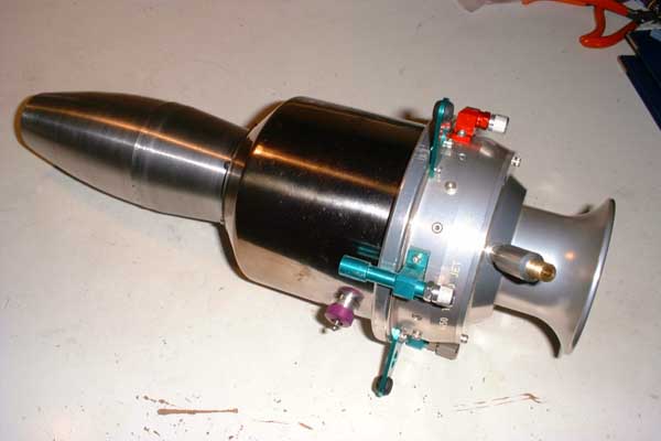
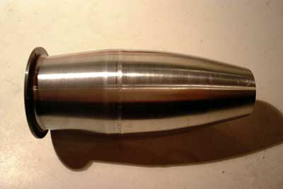 Today I just could spare the time to
sand the exhaust nozzle of the engine on my lathe. Little work and much effect, thats the way I like it ;-). Prior to sanding it was corroded blackly all over, probably due to the fingerprints
and the heat. It surely will discolour again once the engine is running but I will wipe off all the fingerprints prior to each run (if I dont forget it) so it will discolour equally. After sanding it is
very important to clean the bed of the lathe thoroughly as to remove all abrasive deposits to prevent damage from the lathe.
Today I just could spare the time to
sand the exhaust nozzle of the engine on my lathe. Little work and much effect, thats the way I like it ;-). Prior to sanding it was corroded blackly all over, probably due to the fingerprints
and the heat. It surely will discolour again once the engine is running but I will wipe off all the fingerprints prior to each run (if I dont forget it) so it will discolour equally. After sanding it is
very important to clean the bed of the lathe thoroughly as to remove all abrasive deposits to prevent damage from the lathe.
Added 12/19/2000
 Today I got the turbine wheel back
from a friend of mine who sandblasted it at work.
Today I got the turbine wheel back
from a friend of mine who sandblasted it at work.
On the left sits the damaged turbine wheel, which was clean compared to the wheel salvaged from the Garrett T3 turbocharger. Now it looks like new. Still I have to check how much the balance is affected by the sandblasting.
Added 12/29/2000
 Yesterday I obtained some 0.6mm
stainless (V2A) wire to make the turbulence fences from. I used an electric hand drill with electronic speed control to twist three of the wires together. Inserting into the bores in the mounting studs was quite
difficult to accomplish, way down in the combustion chamber.
Yesterday I obtained some 0.6mm
stainless (V2A) wire to make the turbulence fences from. I used an electric hand drill with electronic speed control to twist three of the wires together. Inserting into the bores in the mounting studs was quite
difficult to accomplish, way down in the combustion chamber.
Finally I did some heat treatment to find out if there is a problem when the wires expand during engine operation, so they are already slightly discoloured.
 The combustor as seen from the
compressor side. The ends of the turbulence fences are simply bent to be hooked together. The original design was the same.
The combustor as seen from the
compressor side. The ends of the turbulence fences are simply bent to be hooked together. The original design was the same.
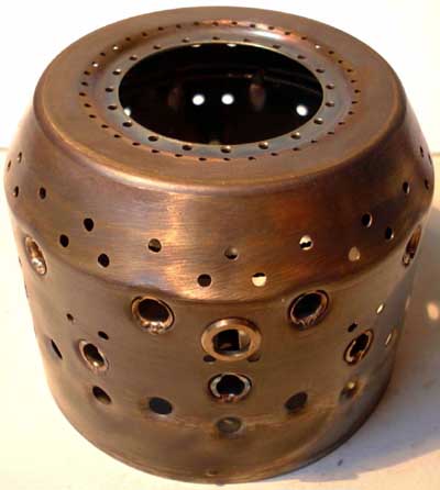 The combustor shown from the
outside. The ring on the combustor wall in the foreground accepts the glow plug.
The combustor shown from the
outside. The ring on the combustor wall in the foreground accepts the glow plug.
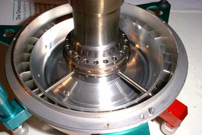
 These are the intake nozzle and the
compressor diffusor. Very beautyfully machined parts! The tube projecting from the intake nozzle contains a ball valve and guides starting air from the scuba tank to the starting nozzle ring,
which is an integral part of the intake.
These are the intake nozzle and the
compressor diffusor. Very beautyfully machined parts! The tube projecting from the intake nozzle contains a ball valve and guides starting air from the scuba tank to the starting nozzle ring,
which is an integral part of the intake.
The center of the diffusor holds a carbon seal (barely visible) to prevent compressor delivery air from leaking into the area between compressor wheel and diffusor.
 This picture shows the other sides of
the intake nozzle and the compressor diffusor. The diffusor vanes are machined from a single piece of aluminium, and at the circumference a second row of straightening vanes is located.
This picture shows the other sides of
the intake nozzle and the compressor diffusor. The diffusor vanes are machined from a single piece of aluminium, and at the circumference a second row of straightening vanes is located.
On the intake nozzle the three starting air orifices are just visible. High pressure air applied to the starting air port impinges onto the vanes of the compressor wheel and spins up the rotor up to 20krpm. With the combustor burning the engine will then reach self-sustaining speed.
 And another picture of the rotor, this
time assembled with the shaft tunnel.
And another picture of the rotor, this
time assembled with the shaft tunnel.
Added 01/07/2001
Finally the spare parts arrived! Immediately I terminated any other occupation to continue work on my Sophia engine (quite difficult to explain to girl friend that theres something one has to do most urgently ;-).
And now again some pictures:
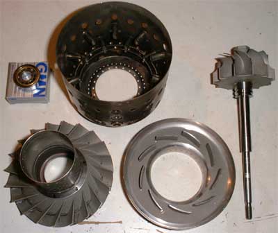 These are the components that have
been changed or had required repair. The lower two components form the nozzle guide system for the turbine and are mainly cast components that have been machined afterwards. The turbine wheel still has to be ground to
to fit into the radial exhaust guide system shroud. So I machined a small mounting attachment for my Dremel mini-drill so that it will fit into the tool holder on my lathe. It took some three
grinders, but finally the wheel fits perfectly into the shroud.
These are the components that have
been changed or had required repair. The lower two components form the nozzle guide system for the turbine and are mainly cast components that have been machined afterwards. The turbine wheel still has to be ground to
to fit into the radial exhaust guide system shroud. So I machined a small mounting attachment for my Dremel mini-drill so that it will fit into the tool holder on my lathe. It took some three
grinders, but finally the wheel fits perfectly into the shroud.
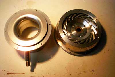
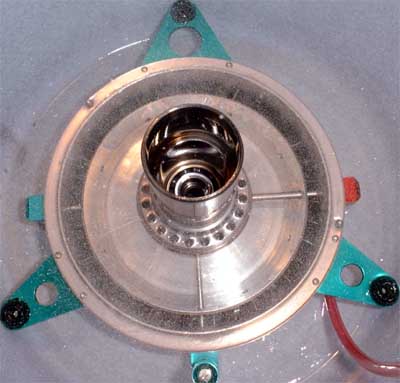
 This is a picture of the compressor
diffusor with the shaft tunnel already in place along with the fuel and oil fittings, and the combustor with exhaust guide system (just to be sure the parts fit correctly).
This is a picture of the compressor
diffusor with the shaft tunnel already in place along with the fuel and oil fittings, and the combustor with exhaust guide system (just to be sure the parts fit correctly).
Afterwards I connected the Kavan gear pump to the fuel inlet and checked the nozzles. At first it seemed as if three nozzles were completely clogged and another two at least partially. After about half a litre of kerosene went through them, it seemed the nozzles became better and better, and finally all of them were blowing a beautyfully atomized fuel mist. But I guess before I start the engine for the first time I will pump another five litres through the nozzles to solve all deposits and wash them out. Then I might take some pictures of the injection system working.
 Here you can see the small space
between inner and outer combustor liner through which the fuel is injected. When correctly assembled each of the fuel nozzles is located adjacent to one of the small air holes in the outer combustor liner flange. The inrushing
air aids the atomization process.
Here you can see the small space
between inner and outer combustor liner through which the fuel is injected. When correctly assembled each of the fuel nozzles is located adjacent to one of the small air holes in the outer combustor liner flange. The inrushing
air aids the atomization process.
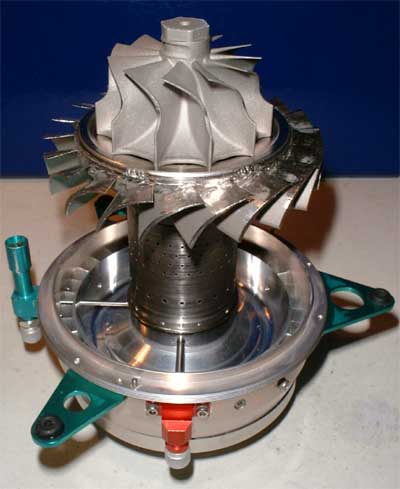 The beast begins more and more to
look like a jet engine ;-). Here the axial NGV and the turbine wheel are attached to the shaft tunnel / compressor diffusor assembly to show the orientation of each. For final assembly the outer combustor liner
will have to be put on first.
The beast begins more and more to
look like a jet engine ;-). Here the axial NGV and the turbine wheel are attached to the shaft tunnel / compressor diffusor assembly to show the orientation of each. For final assembly the outer combustor liner
will have to be put on first.
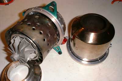 Here the engine core is shown with
the combustion chamber in place completely. On the right sits the outer engine cover.
Here the engine core is shown with
the combustion chamber in place completely. On the right sits the outer engine cover.
 What a cute looking compressor! The
engine cabinet is closed, just the compressor cover and the exhaust nozzle need to be attached. Unfortunately some of the screws seem to be missing, so I will have to figure out a source for M2.5 stainless
inbus screws. One thing that worries me more is that I have one M3 screw left and I dont know where it belongs. But as I received the engine disassembled it might well be possible that some screws had been
interchanged unintentionally.
What a cute looking compressor! The
engine cabinet is closed, just the compressor cover and the exhaust nozzle need to be attached. Unfortunately some of the screws seem to be missing, so I will have to figure out a source for M2.5 stainless
inbus screws. One thing that worries me more is that I have one M3 screw left and I dont know where it belongs. But as I received the engine disassembled it might well be possible that some screws had been
interchanged unintentionally.
 |
Oh well, here the beauty is. Some of the screws still missing, but as I still have to disassemble it partially again to balance the rotor (yes, next is finishing my balancer) and check the injectors once again, I dont bother about this currently. I guess one of the next pictures will be a running Sophia, perhaps I will also record some sounds, or if a friend of mine borroughs me his camcorder I might publish a short video for download.
Added 01/30/2001
 Today I disassembled the J-450 once
again to accomplish final balancing of the turbine wheel (as I just finished my balancer) and to check the injection nozzles for equal atomisation. This is the picture of the fuel system working I
promised some time ago. It was an unbelievably messy experience, I promise, you wont want to smell this. This picture is taken approximately half a second after activating the fuel pump, you can easily imagine the
clowd of kerosene mist after ten seconds of operation. I found two of the fuel nozzles to be partially clogged (insufficient atomisation), and cleaning with a thin wire through the nozzle orifice wouldnt solve the
problem. What I found to be quite effective is a small syringe, filled with acetone and equipped with a silicone rubber hose at the tip. This hose is
then pressed on the nozzle to be cleaned and the acetone ejected. The acetone is allowed to act on the deposits for a minute and then the fuel pump is activated. This way I got all of the fuel
injectors free. I hope they will stay free during operation, but I ran about five liters of kerosene through them without problems, so I guess they will work just fine as long as theres a filter in the
fuel line. Next picture will be one of a (running?) turbine on a test bed.
Today I disassembled the J-450 once
again to accomplish final balancing of the turbine wheel (as I just finished my balancer) and to check the injection nozzles for equal atomisation. This is the picture of the fuel system working I
promised some time ago. It was an unbelievably messy experience, I promise, you wont want to smell this. This picture is taken approximately half a second after activating the fuel pump, you can easily imagine the
clowd of kerosene mist after ten seconds of operation. I found two of the fuel nozzles to be partially clogged (insufficient atomisation), and cleaning with a thin wire through the nozzle orifice wouldnt solve the
problem. What I found to be quite effective is a small syringe, filled with acetone and equipped with a silicone rubber hose at the tip. This hose is
then pressed on the nozzle to be cleaned and the acetone ejected. The acetone is allowed to act on the deposits for a minute and then the fuel pump is activated. This way I got all of the fuel
injectors free. I hope they will stay free during operation, but I ran about five liters of kerosene through them without problems, so I guess they will work just fine as long as theres a filter in the
fuel line. Next picture will be one of a (running?) turbine on a test bed.
Well, thats it for today, more to follow when progress commences. So please stay tuned!
It has been quite a long time since my last post to this part of my page since my interests somehow focused more on the larger engines... But on 04/17/2004, a backyard fair at my friend Christians modelling shop was the opportunity to try a start of the Sophia. Long before, I constructed a small test bed from rigid plywood for the engine and all its accessories. I also had to modify the compressor nut a little to incorporate a neodymium ring magnet in order for the RPM pickup system to work properly. At this time, I went over the complete engine for a final check-up.
Yet I didnt know the correct ECU settings for the combination of fuel pump, oil pump and engine. And since there are more than 15 parameters to adjust, I was a little confused how to proceed. Finally, I decided to chose the standard settings and adjusted paramerters for maximum EGT and RPM rather conservatively.
 |
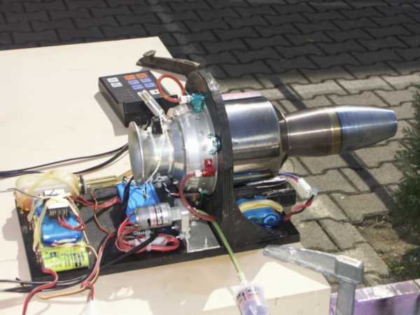 |
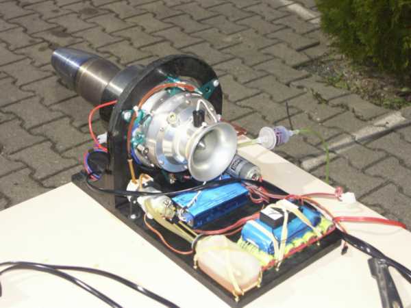
So here we are and the unit is waiting to be fired up (actually, these photos were taken after the first runs, easily to be seen from the discoloured exhaust nozzle - thanks Robert). The test bed incorporates all the engine accessories, ECU, batteries and oil tank. The fuel tank was placed below the table.
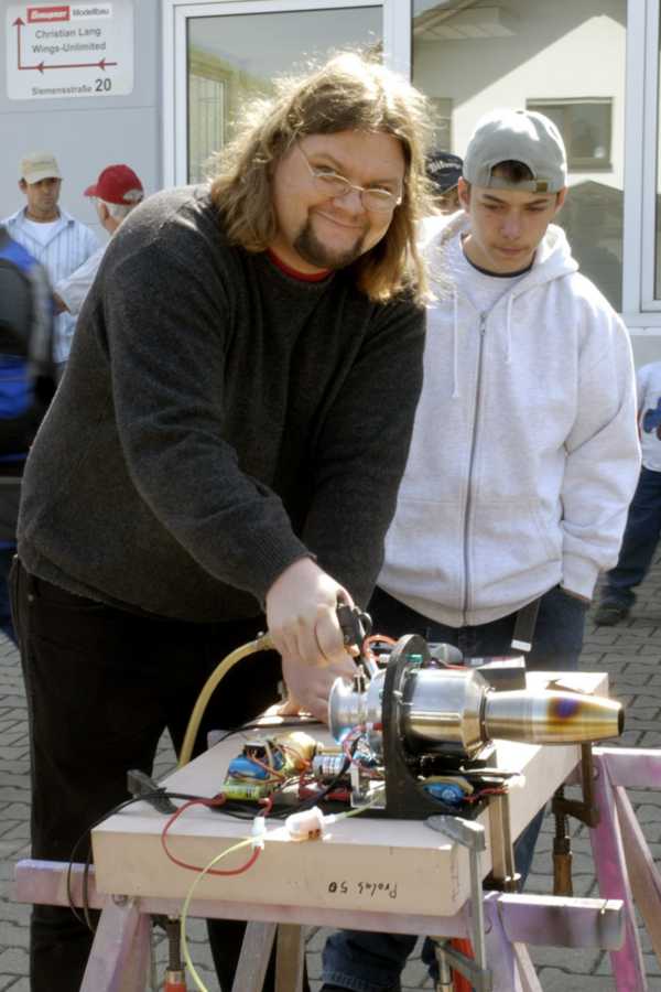 |
Me about to start the engine... Patrick, from our aeromodelling clubs youth group, is keeping an eye on the EGT. Air pressure from the compressor was just at the limit and since the air line was quite long, acceleration to idle was not that easy. Ignition of the finely atomized fuel with the glow plug was astonishingly smooth and easy, but the ECU increased fuel flow too quickly so the engine did some coughing and sputtering and a lot of flames came from the exhaust. We had several shutdowns from excessive EGT during the starts (fuel burning in the thrust nozzle and not in the combustor where it should). But finally we got the engine a few times to self sustain and stabilise at 90krpm. EGT at that speed is very low at just about 400°C. And heres a short video clip of one of the successful starts (thanks Ingo).
Sophia450.mpg (3MB)
When I started cooling the engine after the run, the others launched their model caes, so this noise didnt originate from the engine ;-). But to be honest, the sound of the Sophia is a little thin. I like the fat rumble of the larger ones (APUs) much more...
Whats left to do? Finding correct settings of the ECU so the fuel is admitted more slowly, reducing the lube flow to the engine (it almost consumes as much oil as fuel, easily to be seen as blue puffs of smoke from the exhaust when the engine runs...) and - mounting it on a suitable model ;-).
New Acquisition - please klick here to compare the J-450 with the J-850!