05/01/2004 Once again coincidence and a little luck gave me the opportunity to purchase a Sophia J-850 engine for comparably little money. Since I was really intrigued by the craftsmanship of the J-450, I had a go.
I had been told by the seller that the engine was in operational condition, only the front cover had some minor dents. Well, well...
When I finally received the unit, at first glance it actually appeared to be a really nice one in good condition. The bearings were very smooth but from the discoloration of the thrust nozzle it was obvious that it had a lot of running time.
The J-850 is significantly lighter than the 450 but its still heavier than KJ-66 style engines which produce about the same thrust.
What made me immediately suspicious (...after removal of the thrust nozzle for cleaning...) was that the turbine shroud revealed some traces of contact with the turbine wheel. So a complete teardown was scheduled.
Disassembly of this engine is much simpler than in case of the J-450. As I removed the housing, lumps of fryed grass fell out. many of the holes of the outer combustor liner were partially or totally clogged with grass. Yet, there was no other debris inside the engine than grass. Either the pilot of the aircraft that was equipped with this engine always taxied behind the lawn mower, or the air intake of the craft was placed in the wrong position. If the contamination had resulted form a crash, there must have been found soil and other debris inside the engine and the compressor would have shown traces of FOD which it doesnt.
I soaked the compressor diffusor a few hour in water to get the grass out that had accumulated there - also a considerable amount. I really wonder how this engine still ran with that much grass inside. At least it must have run with significantly decreased performance.
A closer inspection of the outer combustor liner revealed that the flame holder fences (just the same as in case of the J-450) had burnt through and pieces must have gone through the turbine. And this was the reason for the metal-to-metal contact at the turbine wheel and the shroud. Small pieces of metal had been sputtered to the exposed surfaces of the turbine wheel and the NGV. So here some work was required.
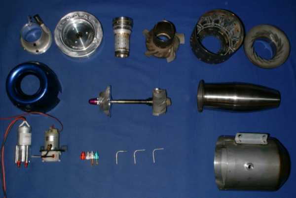 |
This photo shows all the (major) components of the J-850. Only few parts are identical with the J-450, though the craftmanship of the latter appears to be better.
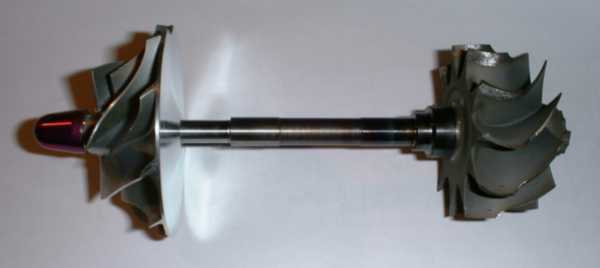 |
The major difference between the 850 and its predecessor is the completely different rotating assembly. The compressor is larger (now 65mm diameter compared to 60mm in case of the 450) and it has only got ten vanes (five long and five short) while the turbine wheel is smaller (56mm compared to 60mm) and very much lighter. I guess, regarding acceleration characteristics, this engine wont be much slower than an engine with an axial turbine wheel.
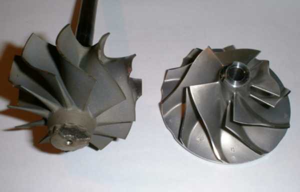 |
The surface quality of the compressor wheel is very good and I guess, at the rated 130krpm it produces a pretty high pressure ratio. At the turbine wheel, I had to slightly shave the leading faces of the vane tips where some of the debris form the broken flame holder fences have accumulated. Yet, fortunately the wheel has not been damaged by this procedure, just the same as in case of the NGV displayed below.
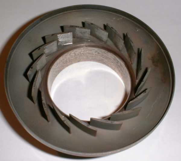 |
The NGV is one of the major differences between this engine and the J-450. Most of the deflection of the hot gas is now done in the radial part of the NGV (which now has got 16 vanes compared to the nine of the 450).
 As a balance, the axial part
of the NGV has only got five vanes. Actually, I dont think they will do much deflection at all since there is so much clear space between them. They rather act as a centering spider for the outer combustor liner. The funny
thing about this component is that it obviously is a modified form of the original axial NGV of the J-450 that had 20 vanes. Sophia simply cut off three vanes in sequence and left every fourth in place. They probably
had the store full of expensive Hastelloy castings... ;-)
As a balance, the axial part
of the NGV has only got five vanes. Actually, I dont think they will do much deflection at all since there is so much clear space between them. They rather act as a centering spider for the outer combustor liner. The funny
thing about this component is that it obviously is a modified form of the original axial NGV of the J-450 that had 20 vanes. Sophia simply cut off three vanes in sequence and left every fourth in place. They probably
had the store full of expensive Hastelloy castings... ;-)
 |
The outer combustion liner appears to be pretty much the same as used on the J-450. Even the burnt flame holder fences look similar ;-) (see below).
 |
Already about one third of the material of the fences must have gone through the turbine. Considering this, the engine still looks pretty good. I thought that such an event would have caused more damage.
Its always difficult to find a suitable material to replace components that have to operate in such a hostile environment. The original wire the fences were made off was highly ferromagnetic. But I dont think it is made of steel, this would have degraded way too quickly. Maybe it has got a high nickel content which causes the magnetic properties. At first, I considered to use stainless safety locking wire but thermal properties of plain stainless arent too good, and I really dont want to have the wires fail any time soon again. So I checked several brands of wires for electric heating elements. Finally I stuck with a material designated Isachrome 60 which consists of 15% chrome, 20% iron and the nickel as the remainder. It is slightly ferromagnetic and is rated for prolonged operation at 1150°C at free air. I hope this material is up to the task but I guess Ill have to check regularly.
 |
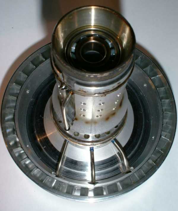
The shaft tunnel of the J-850 basically resembles the one of the 450 but its made of aluminium alloy instead of the stainless (probably to safe weight). It now is equipped with a heat deflector and has got a separate oil feed pipe to the rear bearing (Ive already seen these modifications on later models of the Sophia J-450). Preload has been altered to the front bearing while the injection system with the ten atomisers has been kept. Since the bearings appear to be in pretty good condition, I decided to leave everything in place and only clean it and check the injectors to operate flawlessly.
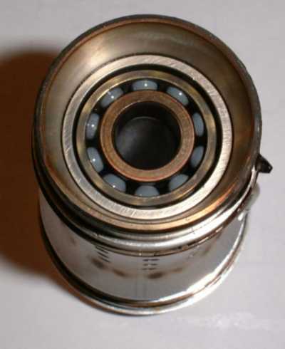 The bearings are probably GMN brand since they are of the same construction with ceramic balls and the strong, machined brass cage as the ones in the J-450. To tell from the very minor
discoloration of the inner race of this rear bearing, there isnt any thermally induced problem to be expected with this engine. The funny thing (well actually it isns so funny when it comes to a bearing
replacement one day...) is that the bearings are of a size nowhere to be found in other model turbine engines. The shaft has got a diameter of 9mm and the outer race 24mm. This relates to the ISO 609 bearing size.
Consequently the bearings should be 7mm wide.
The bearings are probably GMN brand since they are of the same construction with ceramic balls and the strong, machined brass cage as the ones in the J-450. To tell from the very minor
discoloration of the inner race of this rear bearing, there isnt any thermally induced problem to be expected with this engine. The funny thing (well actually it isns so funny when it comes to a bearing
replacement one day...) is that the bearings are of a size nowhere to be found in other model turbine engines. The shaft has got a diameter of 9mm and the outer race 24mm. This relates to the ISO 609 bearing size.
Consequently the bearings should be 7mm wide.
 |
The oil and fuel feed pipes are now bent in an L shape to allow direct access through the diffuser. This eliminates the need for right angle fittings at the periphery of the diffuser which added significantly to the overall diameter of the J-450. Here the shaft and the compressor diffuser are reassembled and the feed tubes are seated with some Hylomar gasket compound. The diffuser itself is a completely new design, now incorporating a vaneless space of a few millimeters between the compressor wheel and the radial diffuser vanes. I guess this design provides a pretty good efficiency. Another difference thats not to be seen here is the labyrith seal between the shaft lobrication cavity and the area behind the compressor wheel. In case of the J-450, a carbon seal had been used here, but the new design of course is a progress since friction is almost eliminated.
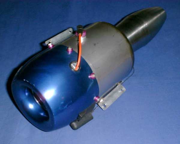 |
Finally...in one piece again. I straightened out the few dents and distortions in the blue compressor cover a little and now the engine looks pretty nice again. Ive got no doubt that it will operate flawlessly - and Ive still got a suitable model jet aircraft (Kangaroo with Sunny Spaceballs design) that awaits building next winter... I know this combination will be a little retro but who cares, it will be a lot of fun anyway :-).