|
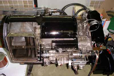
This is my most powerful engine (well, at least at the time of this writing), capable of supplying about 70hp at a weight of 35kg.
It is a Solent Gas Turbine Starter, built in UK by Plessey Dynamics.
I havent run the engine yet, for I will first need to build a test fixture to mount the engine and dissipate the power it generates. If the
engine is started without a proper load, the free power turbine will probably explode.
And now the story of this engine:
After getting infected with the Turbine Virus, I figured out how to get hold of a real thing. At this time I also planned to use the engine
as the powerplant for an ultralight aircraft, but by now I think a little different about this...
At James Engineering Ltd, UK, David James offered me a Solent at a very competetive price. He pointed out though, that the rotor of the
gas generator was stuck, but blamed this to the debris that had settled down in the compressor intake during storage.
So I agreed, and arranged shipping, which was quite difficult at reasonable cost.
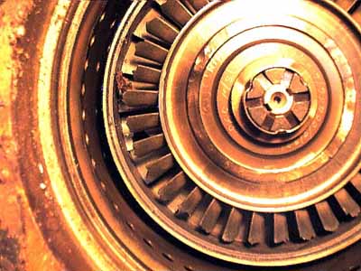
Finally the engine arrived, and after having modified some tools to separate the power-turbine and gearbox from the gas generator assembly, the
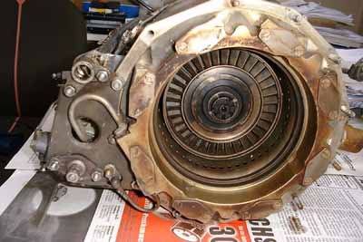
view I had to encounter was rather disappointing. The turbine wheel had thrown all of its blade tips. Further disassembly of the engine revealed even more severe damage.
Both main bearings were destroyed, the rear one ran about 2 mm off of center, causing the main shaft to wobble badly. The compressor rubbed
slightly on the intake, the rear bearing retainer was broken, and two of the NGV blades were burnt. The failure sequence must have been somewhat like this:
First, the main shaft rear bearing must have degraded,
resulting in increasing friction. The governor increased fuel pressure to maintain rpm, resulting in increased EGT. This must have worked a while, until the bearing was damaged so badly that the blades of the
turbine disk touched the shroud. This caused a further increase of friction, and still the governor supplied more fuel to the injectors, so that the combustion flames leaped down to the NGV and the turbine wheel,
causing the metal to soften and break.
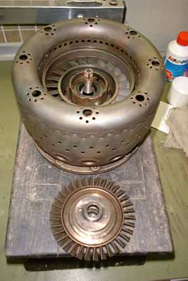
Though David James stated prior to purchase of the engine that he cannot grant any warranty, he supplied another Solent engine to me for free,
which was otherwise in quite bad shape, but revealed still very nice looking gas generator components. Thanks, David!
So next was disassembly of both engines, a lot of cleaning, some repainting, and reassembly of one engine out of the best condition parts of
both.
I already tested all the electric components of the engine and I can tell, this little thing is hot. Just motoring on starter produces almost as
much noise as my turbocharger engine at idle. I believe running this beast must be a real blast!
|