More info on the Solar T-62T-32 engine
Platon and I bought three more T-62 engines from a guy in the Netherlands. My friend Sandor helped me with picking them up. Thank you very much for your time and effort, Sandor!
Two of the three engines wouldnt rotate freely, the other one is in perfect condition. I already disassembled one of the damaged engines and also found a way to repair it. The damage is not that bad so I wouldnt expect there will be a problem with the unit after the job is completed. Yet, some components of the rotating group are affected so I have to be very careful with initial testing. An of course the rotor will have to be re-balanced.
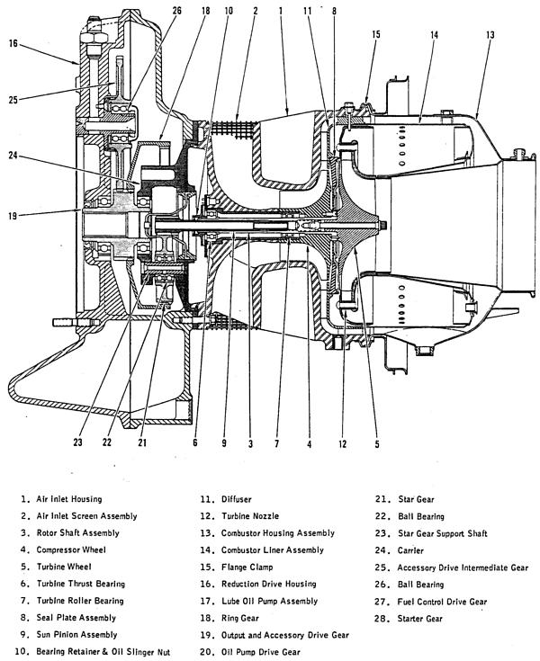 |
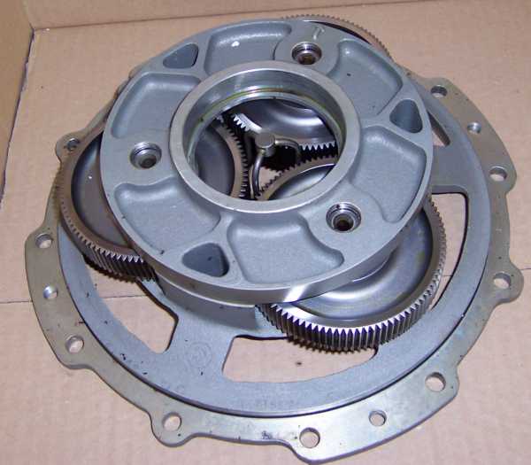
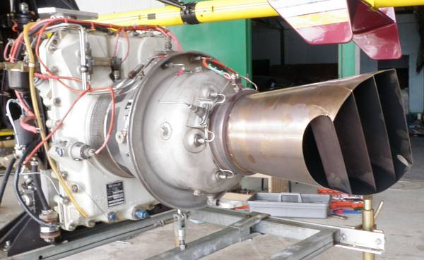
The Solar T-62T-32 has originally been used in the EMU-30/E genset and is a single shaft gas turbine engine with radial compressor and turbine wheels mounted on the same shaft directly back-to-back, thus eliminating the requirement of a bearing in the hot section. This makes the unit a very reliable, troublefree powerplant. The gearbox is located in front of the compressor with the air intake between the gearbox and the engine section. Exhaust is opposite to the gearbox so its quite easy to use the enigne in a hobby project since the hot parts are far away from any other mechaincal installations. The leading particulars are:
Turbine Rotor RPM: 61,091
RPM at the power takeoff pad: 6,000
Rated Power: approx. 150hp
Engine weight: approx. 67kg
Pressure ratio: est. 3.7
Maximum exhaust gas temperature: 630°C
Fuel consumption at rated power: approx. 60l/h
These thermodynamical figures show that the turbomachinery in the Solar has to be quite efficient. Calculations revealed that both turbine and compressor efficiencies have to be round about 82% which is a really good figure considering that the engine has been designed probably in the early 1960s.
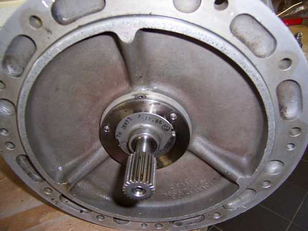
Sandor already dismateled one of the engines with the binding rotor and mailed me a few photos:
 |
These show that this particular unit is generally in a very good shape.
 |
 |
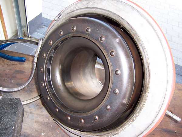
Yet, some traces of turbine wheel rub can be noticed on the heat shield.
 |
 |
 |
And the reason for this is that the heat shield somehow became distorted. Im not absolutely sure what initially caused this warpage but it may have been careless assembly of the components at some time. Anyway, I had to strip the gas generator completely to correct this problem.
 |
 |
Unfortunately, the oil slinger nut that holds the complete rotor in place had been staked too hard to prevent it from coming loose. This caused the thread to fret during the attempt to unscrew it. S**t! The thread on the turbine shaft is quite long and had been damaged only next to the end. So I just machinded the shaft end cylindrical to remove the damaged part of the thread. Its still more than long enough for a secure grip of the nut. Yet, Ill have to find a replacement one to re-assemble the engine.
 |
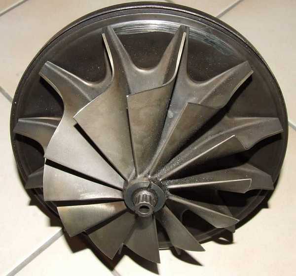 |
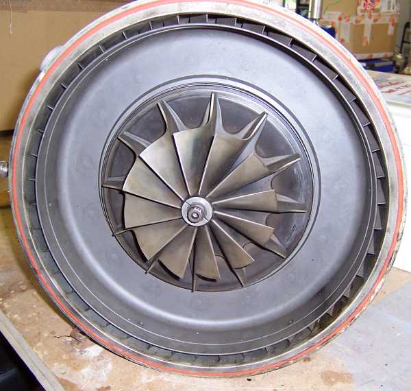
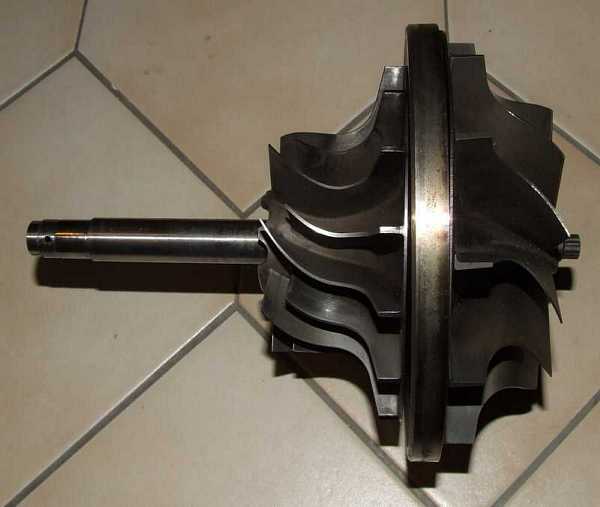
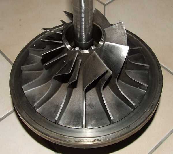
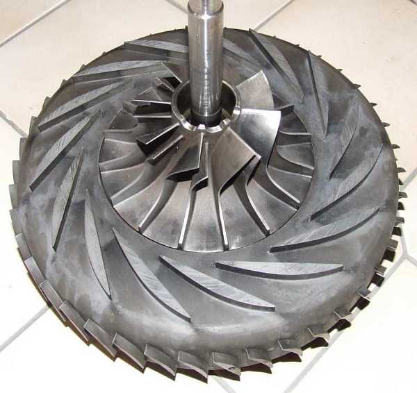
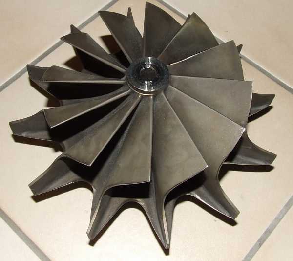
Compressor and turbine wheels still look great. No erosion or impact damage could be found. This means, the engine couldnt have been run for a long time before. Yet, the turbine wheel rub at the heat shield caused some material loss at the rear of the turbine wheel. If spares were available, new turbine wheel would have been required. But since I havent got any spares, well...
 |
 |
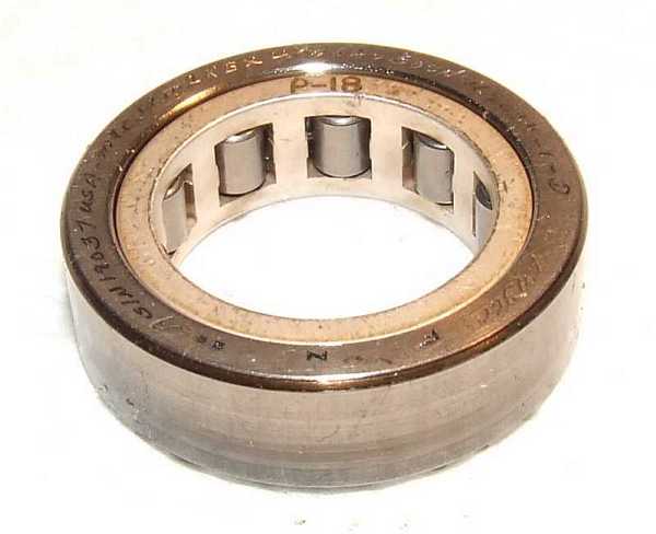 |
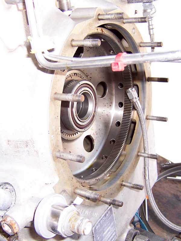
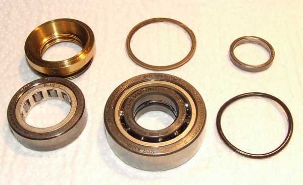
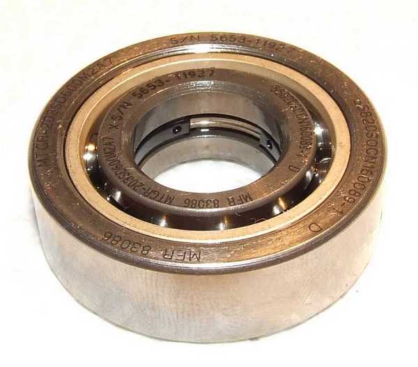
The main rotor bearings are of very high quality and look like new. When turning them by hand, not even the slightest surface roughness can be noticed. Nice!
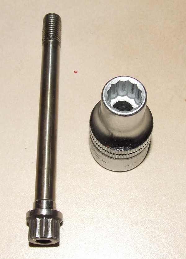 |
Before I was able to further disassemble the engine, I had to remove the turbine bolt. I already bent a spanner on that one so I had to find a high-quality 3/8 twelve-lobe socket. This isnt that easy in a country where usually metric stuff is used. Anyway, a friendly car tool shop owner was able to source one for me. Fortunately, with this tool the turbine bolt came off more easily than I expected. The engine manual states that the bolt has to be replaced everytime it is removed, but once again I havent got a supply of spares so Im afraid Ill have to re-use it.
 |
In the passages of the compressor diffuser, the areas where shock waves form can easily be recognized by the deposition of some dirt. Yet this diffuser has to be very efficient.
 |
The connection of the shaft to the compressor wheel can be considered more or less permanent, it requires cooling of the shaft with dry ice and heating of the compressor and a lot of force to separate the two. Im really glad that I dont have to do this...
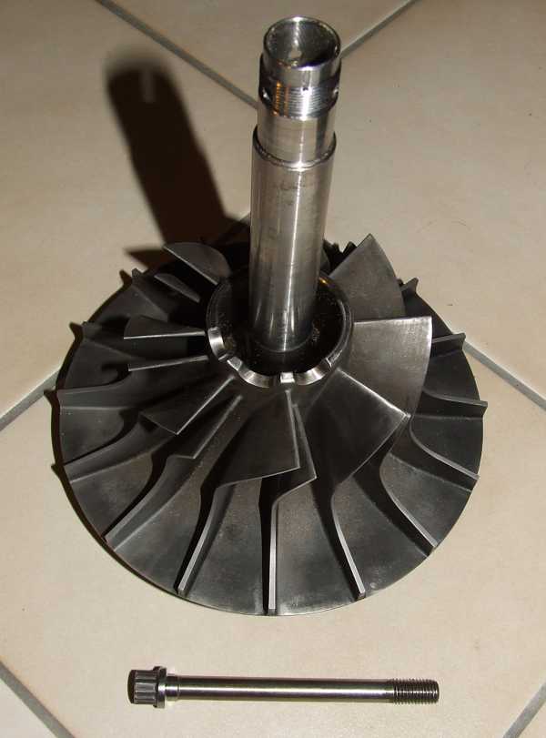 |
I always thougth that the compressor impeller in the Solar T-62 engines was made of an aliminium alloy. But right now that I got the wheel/shaft assembly out, the wheel appears to be made of a different material. Its also quite heavy. So I measured the volume of the impeller/shaft assembly and weighed the parts... Combined specific weight is round about 7g/cm³. This means, with some tolerance in my volume measurement, the wheel may either be made of a titanium alloy (if the shaft is the major part volume-wise and the volume measurement turned out too small) or of stainless steel (if my volume measurement turned out a little too high). The weight of 1720g of the assembly should be fairly accurate. So the compressor definitely isnt made of aluminum alloy which is a good thing to know since these alloys tend to suffer from low cycle fatigue. This means, engine startup cycle limit on the Solar engine will be quite high.
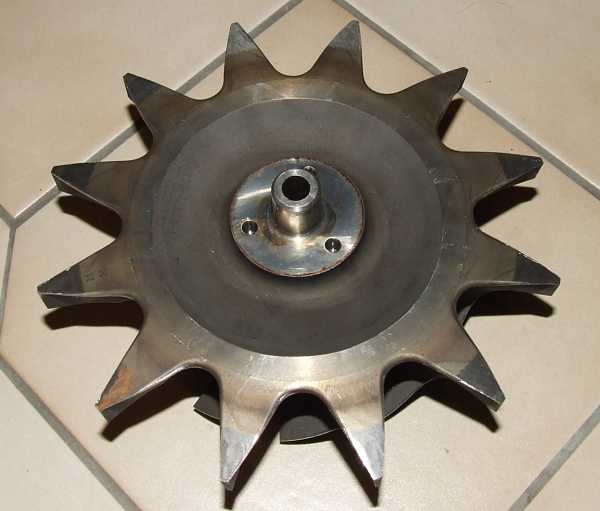 |
Very carefully I re-profiled the back face of the turbine wheel a tiny bit to form a smooth surface again. This will eleimiate the formation of stress in the areas where the rubbing took place. Fortunately the traces of rubbing were not very deep and they were only located close to the turbine wheel tips where the stress in the material isnt that high anymore. Nevertheless that job was quite a tough one, I had to re-sharpen the tungsten carbide cutter probably thirty times...
 |
Right now the re-worked surface has been carefully rounded into the untouched surfaces. this will also help to prevent the formation of stress peaks.
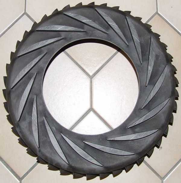 |
 Look at the elaborate airfoils of this diffuser. The diameter ratio of the diffuser compared to the compressor wheel is very high, which is one reason for the high
efficiency of the compressor. Also the edge where the air is guided from the radial to the axial direction is rounded nicely to cause as little flow separation as possible. The axial vanes are quite long once again
so the residual swirl of the compressor delivery air is as low as possible.
Look at the elaborate airfoils of this diffuser. The diameter ratio of the diffuser compared to the compressor wheel is very high, which is one reason for the high
efficiency of the compressor. Also the edge where the air is guided from the radial to the axial direction is rounded nicely to cause as little flow separation as possible. The axial vanes are quite long once again
so the residual swirl of the compressor delivery air is as low as possible.
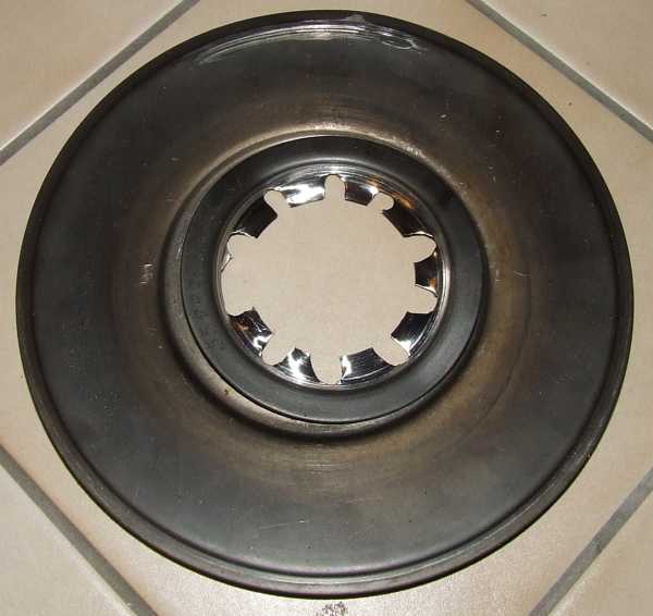 |
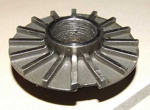
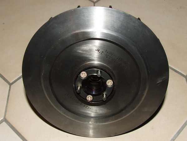
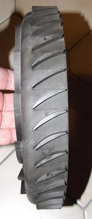
Here weve got the culprit. This is the heat shield, made of a disc of spun sheetmetal. The heat shield retainer is also made of sheet, and is spot welded to the front part of the heat shield (which is a machined component as shown below). Either Ill have to source a new heat shield or Ill just spin the new sheet metal parts and and weld them back in place. Ill have to find some Inconel or Nimonic sheet to make these parts from, but the rest of the job shouldnt be too difficult. Anyway, Ive done a lot of spinning and meanwhile Ive got the hang to it...
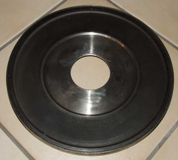 |
Almost appears as if there never has anything been welded to this component...
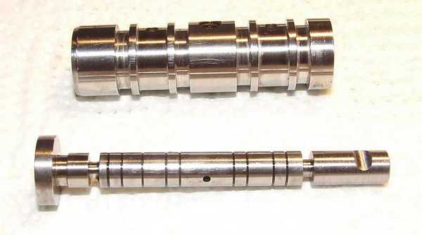 |
One real problem of the T-32 engine is the throttle control shaft. There is a control lever attached to the left of the shaft where the notch is located. The groove next to the notch leaves just about 3mm of steel and this is right through-hardened... This means, even looking at the lever the wrong way may shatter the control shaft at that groove. And this happens more often than one may imagine. My friend Platon already killed two shafts, which made me considering a viable method to repair them. Rhight now, Im doing it like this: Ill cut the surface where the shaft fractured flat and smooth with a mini-grinder (Dremel) on the lathe. Then I use a tungsten carbide drill (3mm or 1/8) to bore a hole of approx. 10mm depth into the shaft. After that, I machine a new top end from tough high-strength steel with a recess thats 12mm long and just fits into the bore (this needs to be accurate!). After that, I machine the other surfaces to size and cut it off. Then the shaft is bonded into the hole using Loctite 648 high strength compound. After that, the notch is milled into the top shaft with the correct angle relation to the fuel control bore. This job takes me about one hour per shaft which is really good, considering the price of a new, matched pair of shaft and sleeve. If this repaired shaft is actually something you would like to have in an engine powering an aircraft of course is a different question...
Btw, the shaft shown above is a repaired one. For those who would like to repair their throttle shafts, heres a DXF and a TIFF of the angular relationship between the control bore and the notch for the control lever, available for download. The drawing is as viewed onto the control lever end of the shaft.
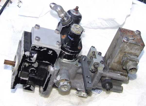 |
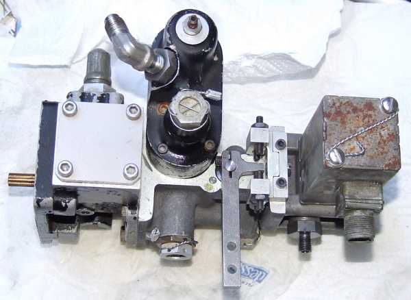 |
Here are two photos of the reassembled fuel control unit. The setscrews are used to limit minimum and maximum fuel flow into the engine. Even though some of the parts are a little rusty externally, these units are shiny like new inside.
Meanwhile I received another heat shield from a damaged engine with the stamped sheet metal disk in decent condition and the machined part damaged - what a nice coincidence... ;-) So I was able to make one out of two. I also constructed a very nice universal flow bench so Im now able to calibrate the FCU as per the manufacturers specs (or whatever parameters seem suitable for the application):
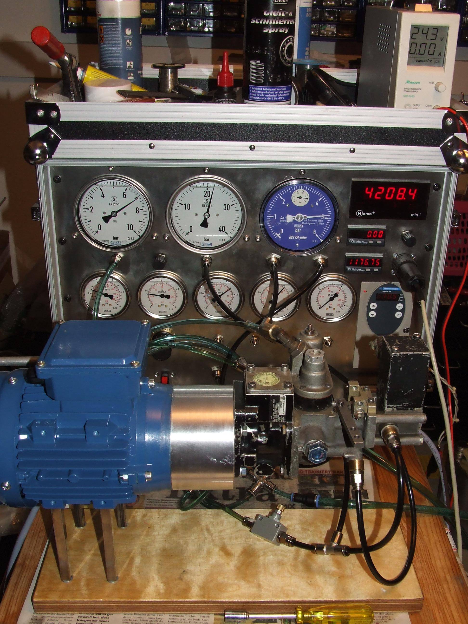 |
It actually turned out that FCUs calibrated as specified by the manufacturer, will run flawlessly out of the box with only minor tweaking of the minimum flow setscrew necessary.
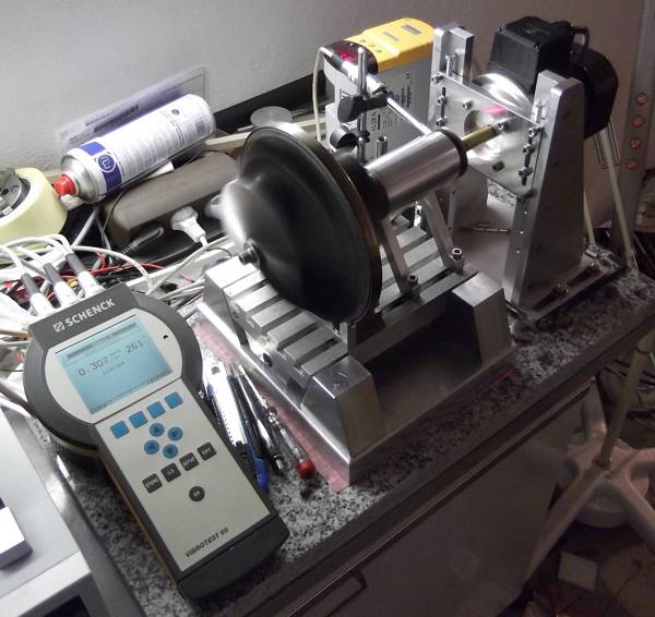 |
The other required piece of equipment was the rotor balancer -- which I also constructed on my own -- well, at least half-way. I was quite lucky to find a Schenck Vibrotest 50 vibration analysis system offered second-hand for really little money (at least for this kind of equipment). Since it had the dynamic balancing module already installed, I only needed to arrange a fixture with some vibration pickups which a good friend machined and assembled for me -- thanks a lot, Werner -- and make a few charge amplifiers to interface the pickups to the Vibrotest. Since this system incorporates digital filtering of the signals, it is very insensitive to bearing noise and vibration of other than the fundamental frequency -- very convenient!
Meanwhile, the engine had been reassembled, test run and already found a new home to power an experimental helicopter. Total engine vibration was well within the manufacturers limits (actually one third of the maximum specs) so I can consider the balancing rig accurate enough...
Here are a few documents that describe some modification on the Solar T-62T-32 engine that we figured out to be quite helpful for convenience or longevity:
Alternator installation on gearbox
 |
This exhaust stack proved quite effective at keeping the tailboom from getting sooty - at very low EGT due to the diffuser/cascade design.