BMW / MTU 6012
On 02/11/2004 I faced another opportunity that I couldnt resist... I was offered a BMW / MTU 6012 with a few parts missing, as the previous owner explained. The 6012 is very similar in many aspects to the previously designed 6002. It had its origin in a time when quite some small turbine engines in a similar power range had been built around the world. Design of the 6012 started in the late 1950s and several different versions had been built. The development of the complete 6012 engine range ended in summer 1966, the last engine was delivered 1971. The initial 6012 was designed as a small turboshaft in the 70...110hp range. Later, an air compressor version was built to power the DO-32 single seat helicopter with rotor blade tip reaction nozzles to provide a torque-free main rotor drive system. This version was equipped with a separate load compressor on the (extended) main shaft. As well, from the original 6012 a thrust version was derived (44daN thrust) to power an experimental motor glider.
The general design has many details in common with other contemporary engines, just like the Garrett GTP30 series or the Solar T-62 and (ecxept the turbine wheel) the British Rover 1S60, the engine features both a single stage radial compressor and turbine wheel. Yet regarding the combustion system, the 6012 differs from any other design of similar size. It utilises a disc combustor with fuel injection through rotating nozzles, located in the hollow main shaft between compressor and turbine wheel. This system permits a very good fuel atomisation over a wide flow range. It has been used on several larger engines and had been pioneered by the French Turbomeca company (Artouste, Marbore, Pimene...).
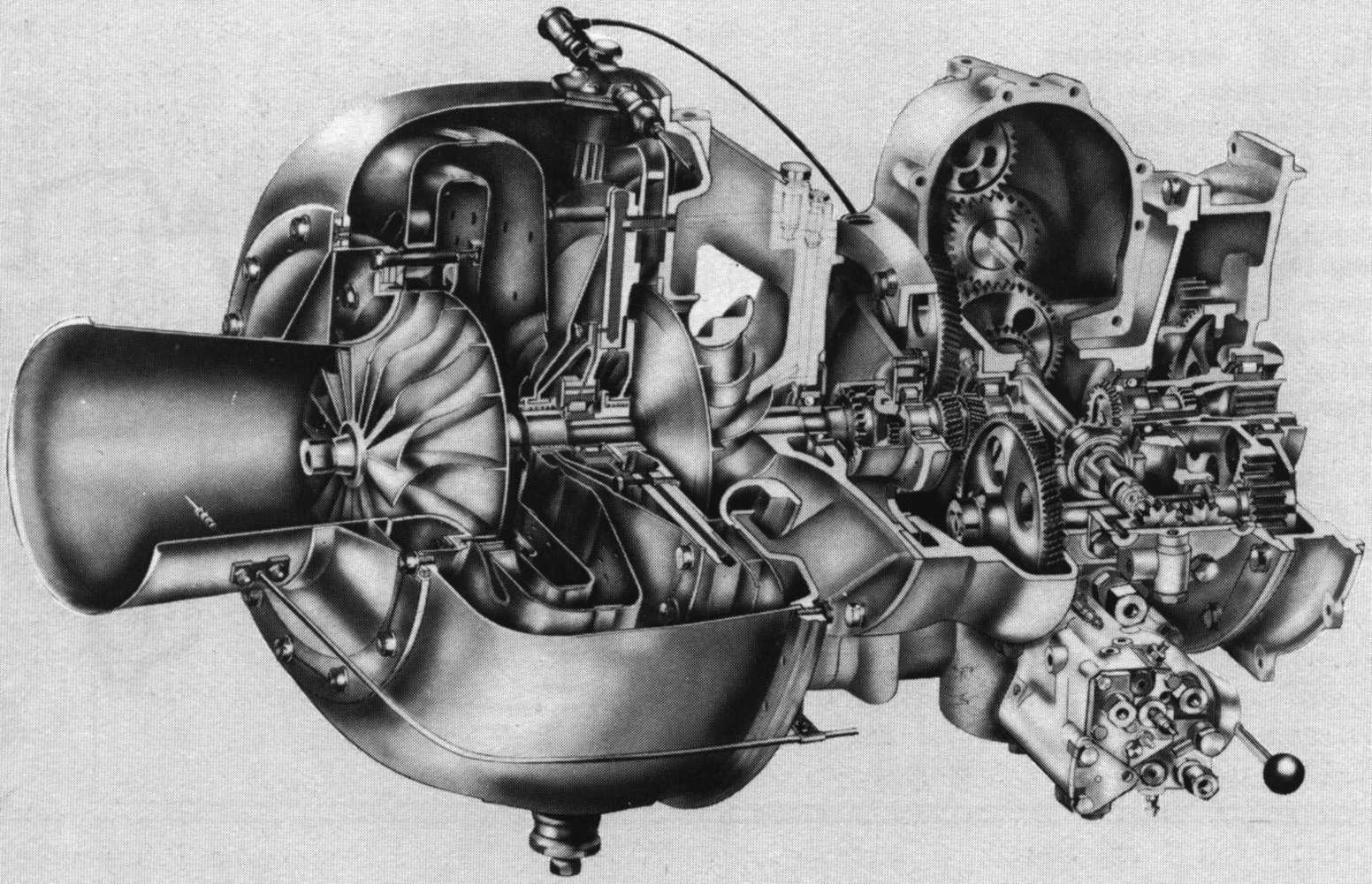 |
Here a cross-section of the turboshaft version of the 6012 is shown. Please click the picture for a higher resolution version.
Some versions of the 6012 had been equipped with a hand crank starter (unfortunately not mine...) and many were used in ground power generators. A total of 278 series engines had been built while 44 were produced solely for development/testing purposes.
These are the technical specifications for the basic 6012 turboshaft unit:
|
First Built: |
1959 |
|
Engine type: |
Turboshaft |
|
Compressor air mass flow: |
0.88kg/s |
|
Number of compressor stages: |
1, radial |
|
Compressor pressure ratio: |
3.1 |
|
Combustor: |
Disc combustor |
|
Number of turbine stages: |
1, radial |
|
Reduction gear ratio (range) |
0.04...0.18 |
|
Engine length: |
713mm |
|
Engine diameter: |
380mm |
|
Dry weight: |
45kg |
|
Shaft power output: |
66kW / 90hp |
|
Rotor speed |
45,000 rpm |
|
Specific fuel consumption |
780g/kwh (approx.) |
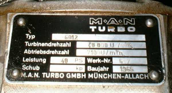 |
This badge makes obvious that my particular engine has been derated to a lower RPM and power output. Yet the general design is identical with the aforementioned units. So I dont think there will be any difficulty to achieve a higher power by properly adjusting the fuel control unit...
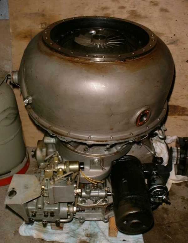 |
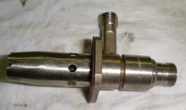
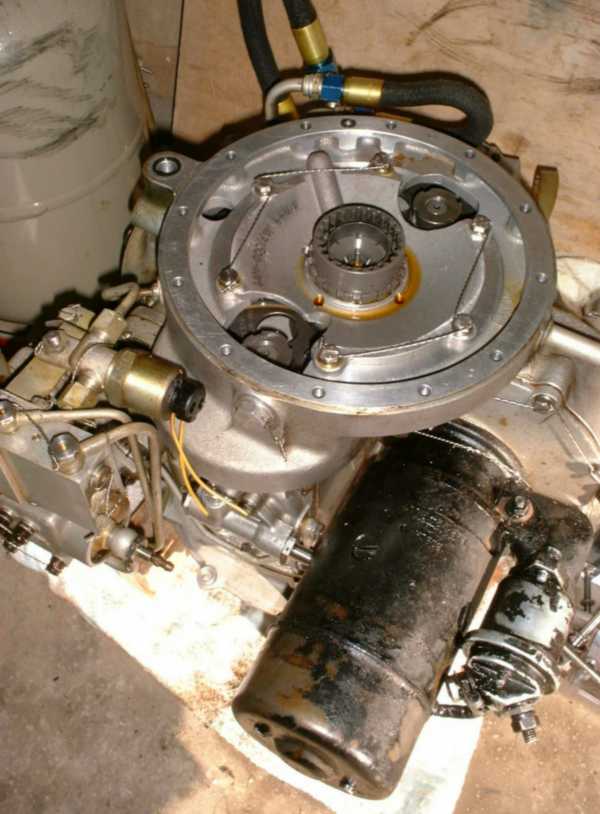
Here the engine is shown, placed on the gearbox output shaft flange. The black motor in the foreground is the electric starter. I guess it adds almost 10kg to the weight. How I would have liked the hand crank version... The gereral condition of the engine is quite good, however there are a few things that might cause me some headaches. One minor issue is that the torch ignitor - probably due to careless handling of the engine - was partially damaged:
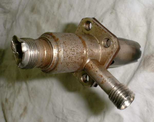 |
As clearly visible, the receptacle of the high tension plug is badly damaged. Also the air shroud on the other side is slightly distorted (not visible in this photo). The whole ignitor seems to be a standard component, made by Bosch. I might try to get a replacement but Im afraid they probably dont make this type any more for a long time. For the time being, I decided to attempt a repair:
 |
The reapir turned out quite well, the damaged portions of the HT plug receptacle have been machined away and the thread has been returned to shape (a plug will show how well so...). As well, the spray shroud has been slightly modelled back to its original shape. After having taken this photo, I somehow broke the gasket, so a new one must be cut prior to reassembly.
But all this is peanuts with regards to the other problems: The exhaust diffuser is missing completely. If none can be sourced as an original spare, it must be specifically built. Even though this might not be that difficult, it requires a lot of work. And just in conjunction with this missing part, the second, still more severe problem occured: The exhaust gas thermometer is missing, i.e. the part that is located in the fuel control unit (FCU) is present but the capillary tube to the sensor end (which was mounted to a flange in the exhaust diffuser...) has simply been clipped.
During my attempt to find out how the thermometer was supposed to work, I made a complete mess with spilling oil all over the place (yes the engine was filled with a special preservation oil - not that bad a thing at all). And then the really nasty part began: Since the capillary tube had been pressed close during cutting it off, I sawed off a short piece to have a look at the bore diameter. I still thought it might be a thermocouple, powering some kind of high current/low voltage solenoid in the FCU. But the capillary turned out to have quite a strong wall and a very small bore (outer 3mm, inner 0.7mm). Then I had a closer look at the actuator that mounts on the FCO, and it turned out to be a bellows. Ok, gas thermometer I tought - will be difficult but might be repairable. Then I slightly pressed the bellows - and heard some kind of rustle in the waste basket. Fortunately I had placed the open end of the capillary above the latter. I pressed the bellows again and looked closer this time - there was mercury being spilled from the capillary. And now I have to face a real problem: Either I find an original replacement EGT thermometer or Ill have to construct my own sensor element (Ill need to know the volume required...), source somewhere a length of the proper capillary tube, find a menas to remove ALL mercury from the actuator bellows to be able to remove the old (clipped) capillary and (hard) solder the new one in place. Then the capillary will need to be welded (or high tempreature brazed) to the new sensor element, some length being left as a filling stud. And then the mercury will need to be added in some kind of vacuum apparatus, followed by fusing the capillary tight. And all this without poisoning myself from the mercury vapors. Oh well, not to forget sourcing the required qantity (about 300g) of mercury...
Anyway, I think this engine is worth the effort since it is otherwise in almost mint condition.
02/16/2004 Since theres a minor dent in the combustor casing and a lot of dirt in the compressor intake shroud and wheel I decided to strip the turbine section of the engine. Even though all the dirt on the engine is quite easily removable, there are some locations that simply arent accessible without some disassebly. So today the first work I did on the engine was to separate the turbine section from the gear box.
 |
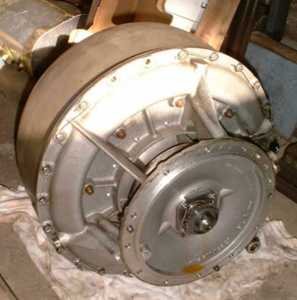 |
After removal of the intake screen and the oil cooler, this task is easily accomplished by removal ot the twelve screws that bolt the two sections together and simply lifting the turbine section off the gear box. There are also three threaded holes in the mounting flange of the turbine section that allow even and careful lifting of the turbine section, provided suitable bolts are inserted and evenly screwed in. The oil feed is routed through a bore in the mounting flange while the return oil flows through an external flange (visible above). It seems to me that the fuel is injected into the central bore of the turbine shaft from the gearbox side. At lease theres something that looks like a small brass nozzle located at the centre of the serrated shaft coupling.
 |
After both sections were separated, I decided to take the turbine section from the garage to the
workshop in the basement. This permits easier work and more comfortable temperatures...
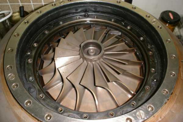
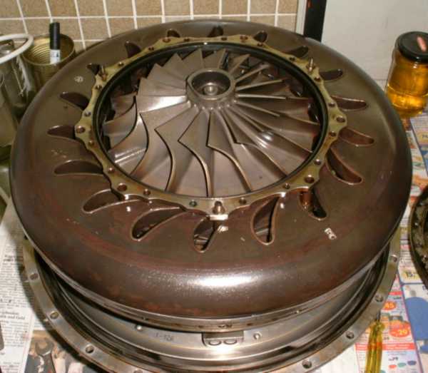
This photo shows the turbine wheel after removal of the shroud. Almost no traces of heat are
visible and the overall condition is very good. Next was the complete removal of the combustor case which proved to be easier than expected.
 |
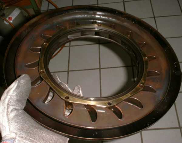
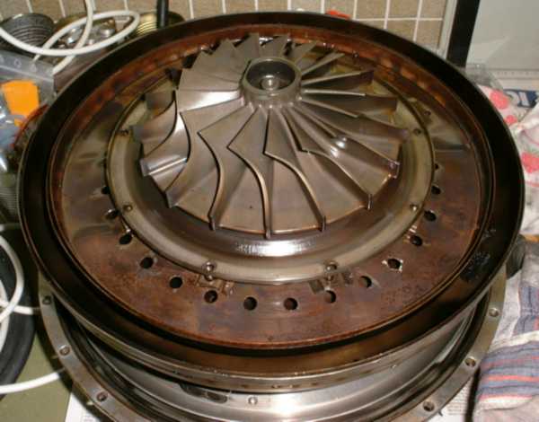
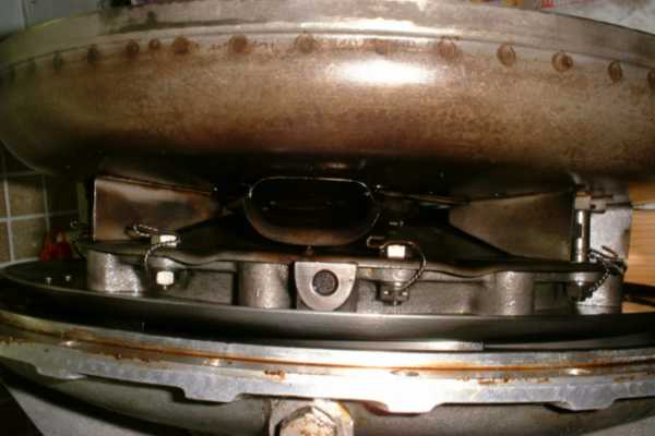
Here the toroidal NGV is shown from the rear. The vanes themselves are hollow so compressed air can flow from the plenum through the nozzle guide vanes to the rear half of the combustor liner. This design has got the additional advantage of very well cooled vanes. I wasnt able yet to pull the NGV ring from the combustor liner. It appears to me that the wall behind the turbine wheel is an integral part with the turbine shroud mounting flange (the machined ring with the many bores shown in the picture above). It may well be possible that I need to remove the turbine wheel together with the shaft from the engine core to get the combustor further apart. I guess Ill find out one of the next days...
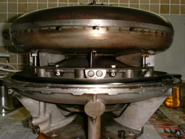 |
Thats another shot of the engine core to show how thin actually the combustor is. You should keep in mind that the upper part of the torus is the NGV and only the lower is the combustor. Such a compact combustor is only possible with the centrifugal injection system, else the fuel spray angles would be too wide so the flame would touch the combustor liner walls. Next will be complete disassembly of the rotor.
02/17/2004 Disassembly of the turbine section continues. Careful application of some tender force removed the NGV from the combustor. The reason for the difficulty removing the NGV ring was some distortion of the combustor walls.
 |
 |
Both halves of the combustor are warped at the primary combustion zone and during disassembly, considerably sized lumps of oil carbon deposits came loose from somewhere inside the combustor (one of them visible at approx. the four oclock position in the above photo). This discovery and the warpage of the combustor walls makes a disassembly of the rotor definitely necessary. I guess that the combustor walls (after they got distorted) project at least partially into the combustion zone so the carbon particles present in the flame get deposited on the walls. Hence the original shape of the combustor parts must be carefully restored and afterwards the parts need to be stress-relieved (by heat treatment) so this wont occur again.
 |
Thats another shot at the side of the combustion section. At the centre of the photo, the flame tunnel is visible. Here the torch ignitor injects its burning fuel vapor to light the main fuel.
Currently Im having the problem that somehow Im not able to remove the serrated disc (one part of the torque coupling between turbine and gearbox) from the turbine shaft. The nut that secures this part to the shaft came off after application of considerable violence ;-). The aforementioned serrated disc (at the centre of this photo) can be pulled clear of the front bearing of the rotating assembly by about 2mm but not any further. To the touch it feels as if there is some kind of rubber or soft plastics gasket between the disc and the turbine wheel tie bolt. I tried the use of a puller (of course with copper-padded claws as not to scratch the parts) and applied a whole lot of force but it wont move further out. Now Ill definitely need at least a detailed cross-section of the engine to understand how these parts are fit together. As long as I dont get the disc removed from the shaft, I cannot further disassemble the engine.
05/01/2004 Still looking for a manual but finally I managed to get the engine apart. The process was delayed several times due to difficulty in finding out how things will separate without damaging anything. After chatting with several people I got a trusty hint from someone that the he had seen spare turbine wheels for the 6012 without any shaft or bolt permanently attached to it. So the tie bolt must somehow be screwed into the wheel. Consequently a special tool had been machined that will be screwed onto the top of the tie bolt and then permits to rotate the bolt. Well, plain right-hand thread at the other end of the bolt and it was out...
Now immediately things started to become difficult again. The turbine wheel still wouldnt come out. Since there isnt any recess or other means to support a removal tool, the force to remove the turbine wheel or shaft has to be transmitted through the front bearing (usually not recommended...). Anyway, I finally decided to go this rout and replace the bearing in case I damage it. I constructed a simple removal tool and whit its help, turbine wheel came off quite easily. Now the two combustion chamber halves could be removed:
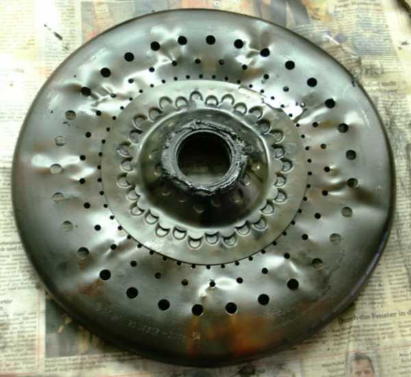 |
Look at this distortion! I really wonder if this rear combustor wall is meant to look like this! And of course, if the combustion heat alone made it look like that. I already tried to tap flat a few of the dents with a wooden hammer - no success. The sheet metal is quite thick and very tough. Ill probably have to get professional assistance here or try to source spare parts...
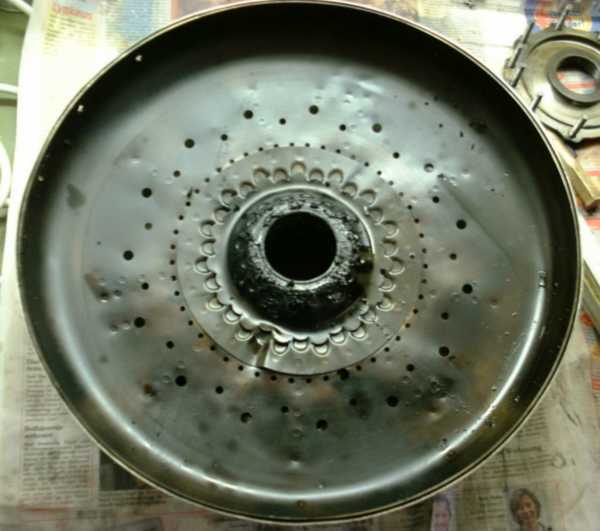 |
The front of the disc combustor shows less distortion except for a sharp knit in the periphery of the sentral section, exactly where the ignition tunnel is placed at the other side. This may or may not be made by intention but I would rather know for sure before I put this part back into the engine. Beforehand Ill have to clean a lot of soot from these parts anyway.
Finally the central roller bearing support could be removed as well and another puller had to be constructed to remove the compressor wheel from the shaft. So here we are:
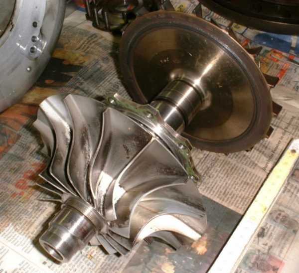 |
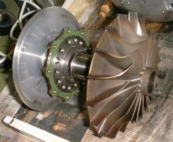
Compressor and turbine wheels have been arranged on the shaft for this photo. Both wheels are approximately 180mm in diameter. The compressor wheel is of simple two-piece design, with rotating inlet guide vanes and radial section (both made of aluminium alloy) permanently attached to a steel hub/shaft. Still some cleaning needs to be done here.
 |
The turbine wheel doesnt look much different from the compressor, at least reagarding vane shape. Here the central bearing retainer is visible which screws onto the central housing of the engine.
Next will be cleaning of the components and then Ill try to straighten out the distorted combustor walls. If this turns out to be successful, reassembly of the power section will commence.