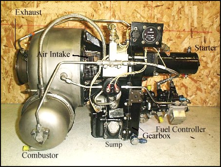
Garrett AiResearch GTP30-67
I consider the Garrett GTP30 series of APUs one of the classic small gas turbine engines. Their origin dates back to the 1960s and there have been quite some similar engines at this time, for instance the Solar T41 APU. All these engines feature both radial compressor and turbine, an overhung rotor shaft construction without bearings in the hot section and a single can combustor located tangentially to the turbine wheel. All this leads to an easy, troublefree operation. These engines will idle at very low temperatures, some fellow turbine collectors report less that 300°C. Since Im currently in the process of inspecting and cleaning the engine, I cannot specify any data myself yet. The GTP30-67 was used in a ground power unit (GPU), the EMU-12/E that was rated 120V/400Hz at 20kW. To conclude from the construction of the engine, it should be capable of much more power but it is probably derated for this application in order to achieve a longer life span. From general construction the GTP30 has much in common with homebuilt turbocharger gas turbines, yet in regards to the level of sophistication they cannot be compared.
I havent got a photo of my engine in one piece yet since I want to have it cleaned first. Actually it isnt very dirty but during the time of storage it has collected a lot of dust in the most impossible corners that needs to be removed. It also has two very minor dents in the air plenum housing that I will try to straighten out. They wont be detrimental with regards to operation but as long as I know they are there I want them to be removed ;-).
 This is a picture I borrowed from Roger Marmion (with his kind permission). It shows his GTP30-67 which he thoroughly cleaned and partially repainted. Please
click the picture to go to his web site.
This is a picture I borrowed from Roger Marmion (with his kind permission). It shows his GTP30-67 which he thoroughly cleaned and partially repainted. Please
click the picture to go to his web site.
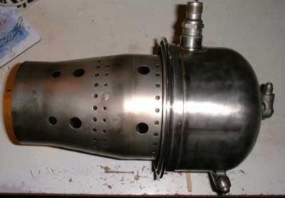
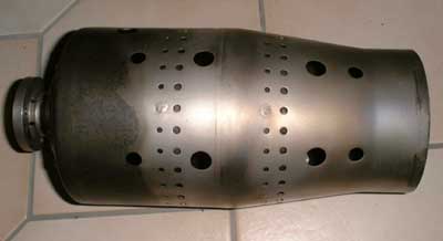 I started disassembly at the hot
section since this end is easiest to access. Heres the flame tube, quite a simple design that could possibly be copied for a turbocharger turbine engine. Total length is approx. 300mm and the diameter at the discharge port
about 100mm. The four rows of small holes allow cooling air to enter the combustor. Inside the tube beneath these holes there are deflection rings that direct this air axially to stay close to the walls.
I started disassembly at the hot
section since this end is easiest to access. Heres the flame tube, quite a simple design that could possibly be copied for a turbocharger turbine engine. Total length is approx. 300mm and the diameter at the discharge port
about 100mm. The four rows of small holes allow cooling air to enter the combustor. Inside the tube beneath these holes there are deflection rings that direct this air axially to stay close to the walls.
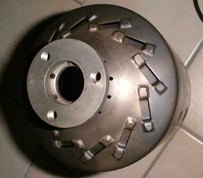 Heres the top flange of the
combustor. It bolts to the injection nozzle and locates the combustor housing cap in between.
Heres the top flange of the
combustor. It bolts to the injection nozzle and locates the combustor housing cap in between.
This is quite an interesting design of primary air swirlers that seem to produce two counter-rotating air flows in the centre and the peripherial regions of the flame tube. Notice the bores inside the fuel nozzle receptacle, here enters some air to aid atomisation (later to be seen).
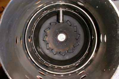 Heres shot into the flame tube. The
two cooling air deflection rings are clearly visible. They seem to do a mighty good job since the flame tube almost isnt discoloured at all on the outside downstream of the cooling orifices. So the walls cannot be much
hotter than perhaps 250°C. Theres also very little soot deposited on the walls, maybe the engine wansnt operated much or it was more or less only idling. Projecting from top you can see the spark plug. Notice how deep it
reaches into the primary zone to provide smooth and reliable ignition.
Heres shot into the flame tube. The
two cooling air deflection rings are clearly visible. They seem to do a mighty good job since the flame tube almost isnt discoloured at all on the outside downstream of the cooling orifices. So the walls cannot be much
hotter than perhaps 250°C. Theres also very little soot deposited on the walls, maybe the engine wansnt operated much or it was more or less only idling. Projecting from top you can see the spark plug. Notice how deep it
reaches into the primary zone to provide smooth and reliable ignition.
For those of you who might be interested in exact dimensions of this combustor liner, Ive sketched a drawing which you can download here. It is a ZIPped DXF file that should be accepted by virtually any CAD software. Yet I dont know if this combustor could be scaled up or down to suit a particular (turbocharger) gas turbine project.
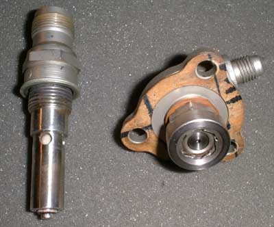 Spark plug and fuel nozzle. This is a
duplex nozzle with integral flow divider so it will provide good fuel atomisation at both low and high flow rates. It features six air swirl vanes that are pressurised through orifices in the fuel
nozzle receptacle (see above). Yet I dont know if I should take it further apart. But since the fuel system had been left open while the engine was on storage I might have a look to be sure any debris is removed that might
have accumulated there.
Spark plug and fuel nozzle. This is a
duplex nozzle with integral flow divider so it will provide good fuel atomisation at both low and high flow rates. It features six air swirl vanes that are pressurised through orifices in the fuel
nozzle receptacle (see above). Yet I dont know if I should take it further apart. But since the fuel system had been left open while the engine was on storage I might have a look to be sure any debris is removed that might
have accumulated there.
 Here you see the complete combustor
with the cap in place. On top the spark plug, to the right theres the fuel nozzle input fitting and at the bottom an automatic drain valve is located. This opens when theres no pressure inside the combustor (engine shut
down) and allows residual unburnt fuel to drain out of the combustor as to avoid consequent hot starts.
Here you see the complete combustor
with the cap in place. On top the spark plug, to the right theres the fuel nozzle input fitting and at the bottom an automatic drain valve is located. This opens when theres no pressure inside the combustor (engine shut
down) and allows residual unburnt fuel to drain out of the combustor as to avoid consequent hot starts.
 And here it becomes clear how
cooling of the spark plug is accomplished. Since the plug projects deeply into the primary zone of the combustor, it will get mighty hot. Through the four holes that are located in the plenum area, relatively cool
compressor delivery air flows to the space between the outer ground electrode tube and the ceramic isolator. This way the tube is cooled from inside. I guess nevertheless it will get very hot and is probably made of
some special alloy to resist the hostile environment.
And here it becomes clear how
cooling of the spark plug is accomplished. Since the plug projects deeply into the primary zone of the combustor, it will get mighty hot. Through the four holes that are located in the plenum area, relatively cool
compressor delivery air flows to the space between the outer ground electrode tube and the ceramic isolator. This way the tube is cooled from inside. I guess nevertheless it will get very hot and is probably made of
some special alloy to resist the hostile environment.
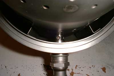
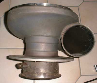
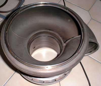
 Isnt this a nice picture? This is the
turbine volute with the combustor can in place. It just projects into the inlet port of the volute with a rather sluggish fit and is held in place at the fuel nozzle flange by the combustor housing cap. This cap is attached to
the turbine housing (plenum) by means of a V-belt clamp.
Isnt this a nice picture? This is the
turbine volute with the combustor can in place. It just projects into the inlet port of the volute with a rather sluggish fit and is held in place at the fuel nozzle flange by the combustor housing cap. This cap is attached to
the turbine housing (plenum) by means of a V-belt clamp.
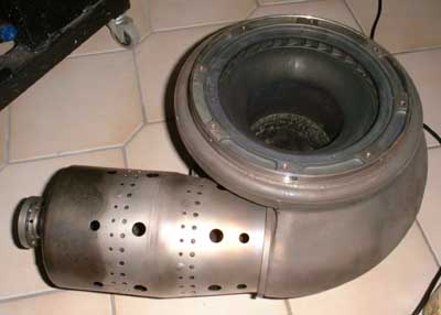
 Heres another view of the turbine
volute, this time from the hot gas entry side. The large flange towards the exhaust port bolts to the turbine housing. At the exhaust diffuser one of the thermocouple receptacles is visible. This engine has two such
ports, one for a temperature gauge on the control panel and one for a pneumatic thermometer that transmits a temperature signal to the fuel control unit to reduce fuel flow in case of too high exhaust gas temperature (EGT).
Heres another view of the turbine
volute, this time from the hot gas entry side. The large flange towards the exhaust port bolts to the turbine housing. At the exhaust diffuser one of the thermocouple receptacles is visible. This engine has two such
ports, one for a temperature gauge on the control panel and one for a pneumatic thermometer that transmits a temperature signal to the fuel control unit to reduce fuel flow in case of too high exhaust gas temperature (EGT).
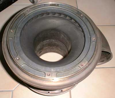 This is the turbine side of the turbine
volute. Actually this part consists of two components: The cast and machined nozzle guide vane (NGV) ring with integral turbine cover and the actual turbine volute, constructed from pressed and welded sheet segments.
The exhaust diffuser is also an integral part of this volute. The NGV section wouldnt come out, it is probably pressed in place. But since all the components are in pretty good condition there really isnt a reason
why I should try to force it. This NGV is a major difference to turbocharger turbines that usually are only equipped with a snailshell volute to guide the hot exhaust gas to the turbine wheel.
This is the turbine side of the turbine
volute. Actually this part consists of two components: The cast and machined nozzle guide vane (NGV) ring with integral turbine cover and the actual turbine volute, constructed from pressed and welded sheet segments.
The exhaust diffuser is also an integral part of this volute. The NGV section wouldnt come out, it is probably pressed in place. But since all the components are in pretty good condition there really isnt a reason
why I should try to force it. This NGV is a major difference to turbocharger turbines that usually are only equipped with a snailshell volute to guide the hot exhaust gas to the turbine wheel.
 I finally decided to remove the NGV
anyway, I simply wanted to have a look at the entry side of the vanes to check them for cracks or other damage - none was found. In this picture you can see that the vanes are almost straight
and quite short. I dont think they will deflect the gas flow from out of the volute very much, I guess they will rather equalise the distribution of the hot gas around the circumference of the turbine wheel.
I finally decided to remove the NGV
anyway, I simply wanted to have a look at the entry side of the vanes to check them for cracks or other damage - none was found. In this picture you can see that the vanes are almost straight
and quite short. I dont think they will deflect the gas flow from out of the volute very much, I guess they will rather equalise the distribution of the hot gas around the circumference of the turbine wheel.
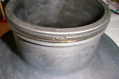 And here becomes clear why the NGV
assembly wouldnt come out easily. There are three sealing rings located at the exhaust port that projects into the exhaust section of the turbine volute. They look very much like piston rings but their ends are machined to
lock into each other, hence sealing the hot section even better. The three rings are arranged such that the overlap of each ring is at a different place at the circumference.
And here becomes clear why the NGV
assembly wouldnt come out easily. There are three sealing rings located at the exhaust port that projects into the exhaust section of the turbine volute. They look very much like piston rings but their ends are machined to
lock into each other, hence sealing the hot section even better. The three rings are arranged such that the overlap of each ring is at a different place at the circumference.
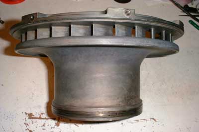
 This picture shows the turbine volute
with the NGV off. Its almost unbelievable how smooth the transition is from a fully circular cross section at the cumbustor liner port to an almost inverse circular section just prior to this port. This part is really
a masterpiece of sheet metal working and welding. It must take huge pressing machines and very tough dies to press this nasty nickel.base alloy into these shapes. It seems that this component is constructed from
four pressed sheet metal parts and several machined parts that make the flanges and seats for the other components to bolt onto.
This picture shows the turbine volute
with the NGV off. Its almost unbelievable how smooth the transition is from a fully circular cross section at the cumbustor liner port to an almost inverse circular section just prior to this port. This part is really
a masterpiece of sheet metal working and welding. It must take huge pressing machines and very tough dies to press this nasty nickel.base alloy into these shapes. It seems that this component is constructed from
four pressed sheet metal parts and several machined parts that make the flanges and seats for the other components to bolt onto.
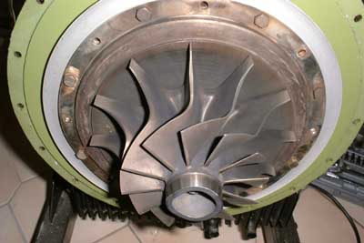 And thats the business end of the
engine. This radial turbine wheel is about 160mm in diameter (100mm at the exhaust), the vane tip height is about 11mm. The turbine is significantly larger than the compressor wheel (146 mm in
diameter and 9mm vane tip height as taken from the manual, but as it seems I wont try to get direct access to it since this would require disassembly of the gearbox). This wheel is in pretty good condition as
well, the fingers will almost stay clean when touching it. I really wonder if this engine was operated for anything else than quality control tests.
And thats the business end of the
engine. This radial turbine wheel is about 160mm in diameter (100mm at the exhaust), the vane tip height is about 11mm. The turbine is significantly larger than the compressor wheel (146 mm in
diameter and 9mm vane tip height as taken from the manual, but as it seems I wont try to get direct access to it since this would require disassembly of the gearbox). This wheel is in pretty good condition as
well, the fingers will almost stay clean when touching it. I really wonder if this engine was operated for anything else than quality control tests.
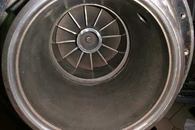
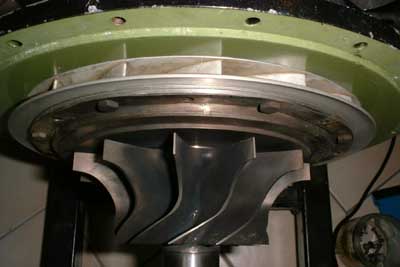 Heres a view from above the engine.
The compressor diffuser vanes are clearly visible and it becomes obvious that compressor and turbine wheel are mounted more or less directly back-to-back. The rear shaft bearing is located very close to the
compressor wheel hub to keep the momentum of the overhung components as small as possible. The front bearing is located in the gearbox that is an integral part with the turbine face plate (the greenish ring visible in
this and the previous photo).
Heres a view from above the engine.
The compressor diffuser vanes are clearly visible and it becomes obvious that compressor and turbine wheel are mounted more or less directly back-to-back. The rear shaft bearing is located very close to the
compressor wheel hub to keep the momentum of the overhung components as small as possible. The front bearing is located in the gearbox that is an integral part with the turbine face plate (the greenish ring visible in
this and the previous photo).
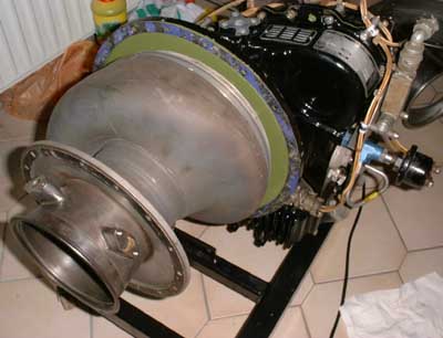 The turbine volute with the NGV is
reassembled already. Today I did some minor straightening at the exhaust gas flange, it seems it had suffered some rough handling during storage, yet the damage was very minor and could easily be repaired. I
also repaired the small dents in the turbine housing with good success and after that made extensive use of a rotating wire brush to clean all the components. Since the front cover of the compressor and the rear half of
the gearbox housing are an integral part cast from aluminium, some of the scews that hold the NGV in place are located in such impossible places that removing or attaching them is like
eating with chopsticks using your feet... ;-)
The turbine volute with the NGV is
reassembled already. Today I did some minor straightening at the exhaust gas flange, it seems it had suffered some rough handling during storage, yet the damage was very minor and could easily be repaired. I
also repaired the small dents in the turbine housing with good success and after that made extensive use of a rotating wire brush to clean all the components. Since the front cover of the compressor and the rear half of
the gearbox housing are an integral part cast from aluminium, some of the scews that hold the NGV in place are located in such impossible places that removing or attaching them is like
eating with chopsticks using your feet... ;-)
 Another view of the turbine wheel, this
time up the exhaust diffuser. The shiny ring at the centre of the turbine wheel is intended as a place to remove material for balancing of the wheel. The two thermocouples arent refitted
yet. Before I proceed with assembly of the engine Ill need to remove it from the stand that I got it in (nice welded steel construction with four wheels at the base) since it seems someone forgot to leave a space for the fuel
controller. I got the engine whitout the fuel pump and sourced one at a different place. So I assume that this engine never ran in its current frame. Strange...
Another view of the turbine wheel, this
time up the exhaust diffuser. The shiny ring at the centre of the turbine wheel is intended as a place to remove material for balancing of the wheel. The two thermocouples arent refitted
yet. Before I proceed with assembly of the engine Ill need to remove it from the stand that I got it in (nice welded steel construction with four wheels at the base) since it seems someone forgot to leave a space for the fuel
controller. I got the engine whitout the fuel pump and sourced one at a different place. So I assume that this engine never ran in its current frame. Strange...
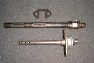 These are the two exhaust gas
temperature sensors. The upper one is a temperature controlled pneumatic valve which is connected to the acceleration controller of the FCU (fuel control unit). Some of the compressor delivery pressure that is used by the
FCU to determine the amount of fuel that could safely be burnt (through a metering orifice) is vented to the atmosphere if the exhaust temperature gets too high. This causes the FCU to believe that the
compressor delivery pressure is low and thus it will reduce fuel flow, causing the EGT to decrease. Yet this shouldnt ever happen during normal, governed operation of the engine. Only in cases of extreme
environmental conditions or if the load or a mechanical failure causes the maximum torque of the engine to be exceeded, the valve would prevent damage to the hot parts of the engine. The lower
sensor shown in the picture is a thermocouple, used to indicate the EGT at the control panel.
These are the two exhaust gas
temperature sensors. The upper one is a temperature controlled pneumatic valve which is connected to the acceleration controller of the FCU (fuel control unit). Some of the compressor delivery pressure that is used by the
FCU to determine the amount of fuel that could safely be burnt (through a metering orifice) is vented to the atmosphere if the exhaust temperature gets too high. This causes the FCU to believe that the
compressor delivery pressure is low and thus it will reduce fuel flow, causing the EGT to decrease. Yet this shouldnt ever happen during normal, governed operation of the engine. Only in cases of extreme
environmental conditions or if the load or a mechanical failure causes the maximum torque of the engine to be exceeded, the valve would prevent damage to the hot parts of the engine. The lower
sensor shown in the picture is a thermocouple, used to indicate the EGT at the control panel.
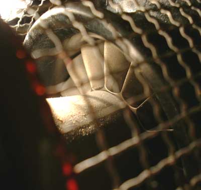 A part of the compressor is visible
here. This photo is taken through the debris guard (wire mesh) and hence proper lighting of the components inside is quite difficult. In bright light all that will be visible is the debris guard and not much more. I wont
disassemble the engine down to this place as this would require disassembly of the gear box. And since the engine is in pretty good condition I dont consider this to be necessary. The compressor wheel
itself is made of forged titanium and is a very beautiful piece of engineering. Due to the tough material the edges of the rotating inlet guide vanes can be machined much sharper than it would
be possible with aluminium alloy as construction material. Yet Ill still need to get a small brush to remove the dust from the parts inside the debris guard... ;-).
A part of the compressor is visible
here. This photo is taken through the debris guard (wire mesh) and hence proper lighting of the components inside is quite difficult. In bright light all that will be visible is the debris guard and not much more. I wont
disassemble the engine down to this place as this would require disassembly of the gear box. And since the engine is in pretty good condition I dont consider this to be necessary. The compressor wheel
itself is made of forged titanium and is a very beautiful piece of engineering. Due to the tough material the edges of the rotating inlet guide vanes can be machined much sharper than it would
be possible with aluminium alloy as construction material. Yet Ill still need to get a small brush to remove the dust from the parts inside the debris guard... ;-).
Bad news - the ignition box of the engine is damaged. It would make a high-pitched whining noise but it wont spark. Also the current consumption was rather low, less than 500mA. I finally decided to open it and since it is a soldered metal can construction I tried to use the household can opener - and immediately ruined it ;-). Anyway, somehow I opened the box and found the complete electronics to be covered in polyurethane foam. After some archaeologists work (the igniter dated from 1968...) I had dug out the electronics. Yes, ELECTRONICS! I expected to find an electromagnetic trembler and an ignition coil, but there is a vintage 1968 silicon (!) power transistor in it that forms a simple flyback-converter. Ill post the schematic as soon as I find some time to enter the free-hand sketch into my CAE system. Anyway, finally it turned out that the spark energy storage capacitor was internally shorted and since this is about the single most important component in the whole igniter, there wouldnt have been a chance to repair it anyway. Yet I could rescue the two connectors so now its time for a modified version of my Bangbox. I considered buying an original spare but I think my wallet wont like this idea too much. Once again, Ill post pictures and the new schematic soon.
 This picture gives a good idea of how
tight the two rotor wheels are actually mounted together. All that is in between is just a rotating air seal (labyrinth type). The solenoid valve visible in the foreground is the fuel shutoff valve that needs to be
energised as long as the engine is running. It simply blocks the passage from the fuel control unit to the injection nozzle. The fuel pressure limiting valve within the FCU will then spill all the fuel back to the input side
of the fuel pump.
This picture gives a good idea of how
tight the two rotor wheels are actually mounted together. All that is in between is just a rotating air seal (labyrinth type). The solenoid valve visible in the foreground is the fuel shutoff valve that needs to be
energised as long as the engine is running. It simply blocks the passage from the fuel control unit to the injection nozzle. The fuel pressure limiting valve within the FCU will then spill all the fuel back to the input side
of the fuel pump.
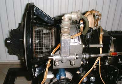
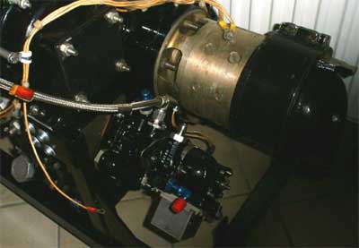 This quite dark photo shows basically
the fuel control unit. The flexible hose ducts the fuel to the solenoid valve seen above. Behind the fuel control unit theres the Russian-built DC generator. It is only rated at 3kW and hence isnt a real challenge for the
engine. Yet it fits onto the power takeoff receptacle like it was made for this application. Even the spline on its drive shaft matches the engine. The cover plate above the FCU protects the starter ratchet shaft from dirt or
corrosion. Usually the starter motor bolts on there, but probably the included generator would be capable of starting the engine as well. Yet for driving something real with this engine, there will need to
be a proper starter motor sourced. So once again I negociated with Bruce Linsmeyer from Avon Aero about a price for some components (I already got the FCU from him). This time Ill get the
starter, an ignition exciter, a starter relay (since the motorcycle relay that I already got would do the job probably only once ;-) and some other smaller components from him. When I get the box I
hope it wouldnt be long until the beast screams for the first time again. Ill just need to make some kind of electrical test fixture to be able to operate all the functions properly and to always be able
to cut the engine immediately, just in case. But this would only require a lot of switches, some small relays, a few lamps and gauges and a nice, rigid metal box.
This quite dark photo shows basically
the fuel control unit. The flexible hose ducts the fuel to the solenoid valve seen above. Behind the fuel control unit theres the Russian-built DC generator. It is only rated at 3kW and hence isnt a real challenge for the
engine. Yet it fits onto the power takeoff receptacle like it was made for this application. Even the spline on its drive shaft matches the engine. The cover plate above the FCU protects the starter ratchet shaft from dirt or
corrosion. Usually the starter motor bolts on there, but probably the included generator would be capable of starting the engine as well. Yet for driving something real with this engine, there will need to
be a proper starter motor sourced. So once again I negociated with Bruce Linsmeyer from Avon Aero about a price for some components (I already got the FCU from him). This time Ill get the
starter, an ignition exciter, a starter relay (since the motorcycle relay that I already got would do the job probably only once ;-) and some other smaller components from him. When I get the box I
hope it wouldnt be long until the beast screams for the first time again. Ill just need to make some kind of electrical test fixture to be able to operate all the functions properly and to always be able
to cut the engine immediately, just in case. But this would only require a lot of switches, some small relays, a few lamps and gauges and a nice, rigid metal box.
Well, I decided not to just make something preliminary but to build a control panel that would be kept for a possible application of the engine later on. I found out that one of the internal wirings of the three-phase RPM tacho generator was molten away. This was probably a result of operating the engine without a proper ground return wire, causing a high current to flow through the ground link inside this generator. Yet it was easily repaired and then I found out that the VDO RPM gauge that Ive still got sitting on my shelf exactly fits this generator. So I did a little drawing and a little milling on my CAD/CAM system and here it is, the control panel:
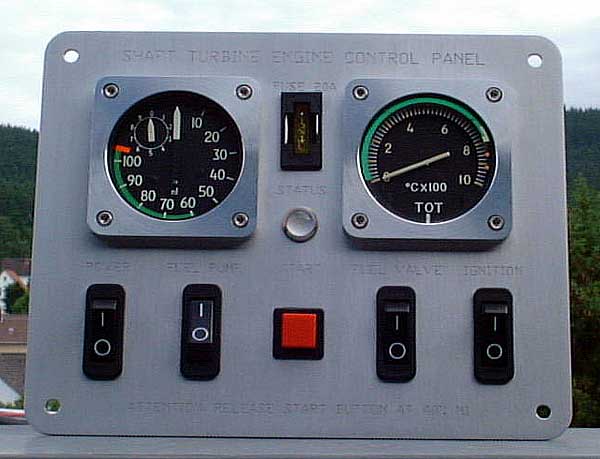
The engraved descriptions can hardly be seen, maybe I should flush them with some dye. This panel measures only 190x150mm² and contains a manual breaker for every major electrical circuit. There are some safety circuits that will shut down the engine in case of severe overspeed or too low oil pressure, as well provisions were taken to avoid the starter to be energised once the engine is running. I will publish a schematic of this control unit if somebody is interested. In this case, please drop me a line. Theres no real electronics in it, just electromechanics (relays, switches) and a few diodes. Nothing really complicated. I guess this panel would make an ultralights dashboard look mighty important ;-).
After another deal with Bruce Linsmeyer from Avon Aero (http://www.avonaero.com) I got an original starter motor (since converting a motorcycle starter seems too much hassle) as well as an ignition exciter and some other smaller components. Yet though I operated the exciter according to the specifications on the type plate, it gave up its ghost after only a few minutes of total sparking time. Seems like I have no luck with these units. Yet Bruce was so kind to send me another one for free, this time everything was ok. The former ones were GLA brand (General Laboratories Assosiates), this one is a Bendix. But since Im always a little peculiar, I opened the second damaged GLA unit as well. After cleaning out all the rubber resin it was covered with, the photo below was taken.
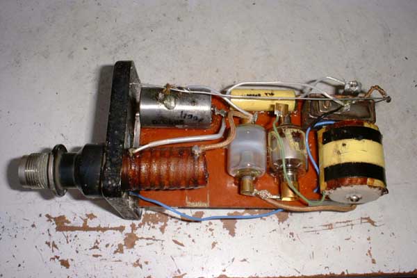
This ignition exciter dates 1966 and is exactly what I had expected. A nice, straight-forward electro-mechanical unit. At the right theres the voltage converter coil with the trembler points as an integral component above. The points are placed in a hermetically tight cabinet, probably filled with some highly isolative gas (SF6 or the like). The yellow capacitor left from the trembler cabinet is the resonant cap, wired in parallel with the points. Left from the transformer coil sits the gas-filled rectifier diode and then the trigger spark gap. Some of its electrodes material had been sputtered onto the glass walls during operation. The series ignition coil is placed in-line with the ignition terinal with the ignition capacitor just above it. All these components are glued to a pertinax plate. On the other site of this plate theres the large energy storage capacitor placed as well as the two discharge resistors. A more detailed analysis of the failure revealed a partial isolation break-down in the secondary of the voltage converter coil. This will reduce the output voltage to a point where the trigger spark gap wont break down anymore. Since the other components are still in a pretty good shape and I managed to open the exciter case without damaging it, I decided to rebuild this unit with an electronic voltage converter. After some hours of design work it became amazingly clear how small actually the electromechanical solution of the sixties is. Anyway I managed to construct the electronic exciter circuit in the same place but I can tell you this wasnt easy. Ill post a picture as soon as the new version is ready for testing.
And here it is:
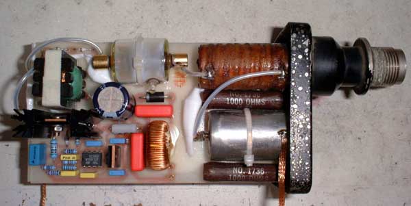
The voltage converter is based on a UC3843 current mode PWM flyback converter chip that allows the construction of a very compact and reliable power supply. Due to the extremely high switching speeds of power MOSFETs, the step-up transformer requires just about 100 turns for the secondary to produce up to 5kV. In this case I used PTFE-isolated PCB patch wire for the secondary because of its superb isolation characteristics.
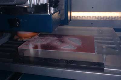 This is a shot of my mill making the
PCB (actually nothing much to see).
This is a shot of my mill making the
PCB (actually nothing much to see).
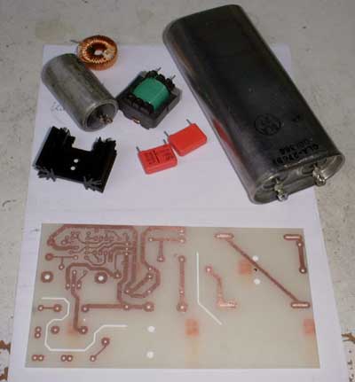 Here some of the components are
shown. The PCB is finished. Top right is the big energy storage capacitor, salvaged from the old, damaged ignition exciter. It is rated 1µF at about 5kV.
Here some of the components are
shown. The PCB is finished. Top right is the big energy storage capacitor, salvaged from the old, damaged ignition exciter. It is rated 1µF at about 5kV.
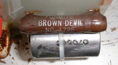 What a nice name for a resistor!
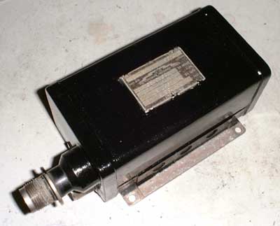 After thorough testing the exciter
cabinet finally is soldered hermetically tight and re-painted. As I found out later (read below) good old Murphy must have found a way into the cabinet just before I shut it tight...
After thorough testing the exciter
cabinet finally is soldered hermetically tight and re-painted. As I found out later (read below) good old Murphy must have found a way into the cabinet just before I shut it tight...
If anybody is interested in the schematics (very similar to the Bangbox but a little simplified and different ignition configuration), please drop me a line.
06/15/2002
Today was a really great day! A few friends, among them Bene from the DIYGasTurbines list,
came over to my place and helped me with carrying outside the GTP30-67. I still had to do some quick modifications this morning since two problems apperared unexpectedly. I had to attach
another ignition exciter since my modified one quit after three snaps this morning (and that after excessive testing yesterday and soldering tight the cabinet...) and the thermal protection switch of
the starter motor turned out to be defective - so I simply shorted it.
But I got these minor difficulties sorted out before the others dropped in. Then after a quick lunch and a look at my other toys, we carried outside the turbine, the two starter batteries, the control panel, some tools and the special fuel mix (80% diesel, 20% gas and you should have seen the look of the guy at the filling station...).
The engine was wired up quickly. Then we disconnected the feed pipe from the fuel nozzle to cold crank the engine in order to bleed the air from the fuel system. Ok, main power on, fuel feed pump on, fuel valve on and starter button pressed. The starter clutch snapped in place and the engine accelerated rapidly. Quickly fuel was pouring from the pipe into a small bucket. The engine tach turned out to work reversely, so I exchanged two of the three phases and it worked allright. Now came the moment of truth. I would be lying if I'ld tell you I wasn't excited and perhaps a little bit frightened, but anyway, if not now when then?
So I set the main power switch on, fuel feed pump on (chuck-chuck-chuck..., a Bendix interruptor pump makes funny noises), ignition system on, fuel valve switch on and... start button pressed. The engine started spooling up and within a second the burner burst into life - wooosh. At first the engine didn't seem to accelerate any faster than on the starter motor alone but when it approached 15% N1 the effect of the combustion became more and more evident. Within about ten seconds RPM reached 40% and I released the starter as described in the manual. The engine continued to accelerate but suddenly it "coughed", the flame seemed to be extinguished shortly to relight again just after about half a second. The engine threw a cloud of unburnt fuel mist, the look was quite spectacular. It was a real luck that the neighbors weren't at home at this time. The engine repeated this for about ten seconds without accelerating above 50% until I shut it down.
After some discussions we decided to try to bleed some more air from the fuel system and disconnected the fuel hose just prior to the solenoid fuel valve. This time we pumped about half a litre through the fuel control unit until it came flowing completely free of bubbles. Then we reattached the hose and gave it another attempt. The engine started up once again (now with the neighbours back home and watching, but warned of what possibly to expect) but this time it happily accelerated above the 50% mark. At 60% the acceleration rate became really frightening and if I hadn't been prepared for this by some other GTP30 owners, I probably would have pushed the main power switch to shut down the unit. From 60% to 100% the engine accelerated in about four seconds. It reached no-load governed speed at 101%, and a consequent run with a calibrated thermometer in the exhaust revealed an EGT of just 290°C at an ambient temperature of probably almost 30°C.
Quickly we had a spectator who turned out to having been a sevice technician at KHD (Klöckner-Humboldt-Deutz, a turbine manufacturing company not far from my town, nowadays
part of Rolls Royce). He heard the engine noise - or should I say "music" ;-) - and thought there was a display or practice of
the fire fighters nearby since there are a few pumps equipped with KHD turbines around. He was really amazed to see a small turbine engine in private hands and enjoyed the further runs very much.
To keep annoyance to the neighbors to a minimum we finished after four runs to 100% and enjoyed the rest of the day smiling... This was fun I can tell you. We had some videos taken and as soon as I'll get them transferred into the PC and converted to a reasonable size format, I'll upload them to my web site.
The fuel consumption of the GTP30 seems to be quite moderate. Well, at least with regards to turbines. For a total of six starts (where the first two werent completed to governed speed) and a total running time of about six minutes it consumed just about one litre of Toms very special mix. I guess it will produce some considerable power with a fuel flow of 30 litres per hour. If we then take into account the price for kerosine or even home heating oil compared to avgas (or mogas which suits our UL aircraft engines), running this engine in such an aircraft could be a real bargain. Only issue is that one will need to top up the tank more often.
Well, here are the clips. You will need the DivX codec to view them. It turned out that this format allowed the least size of the clips while still providing acceptable quality.
Walkabout (1MB) shows the engine from all sides just ready for take-off. Nothing really spectacular but I placed it here anyway.
Start1 (1.8MB) was the first time the engine actually accelerated to governed speed. Notice the nice flame from the exhaust at ignition and the coughing while running at idle speed. I blame this to some air still being trapped in the fuel control unit.
Start2 (2.7MB) shows the engine after we placed a calibrated thermocouple in the exhaust to get some reliable readings for EGT. The EGT meter I mounted to my control panel originated from a helicopter and was calibrated for a type K thermocouple with longer interconnection wires hence the readings on this instrument were a little high (about 20%). Ill adjust it later on. Actual EGT at no-load governed speed was just slightly above 290°C. During acceleration the temperature increased above 700°C momentarily. The coughing was there once again after governed speed was reached but it disappeared a few seconds later. Notice the effect of the jet efflux to the plants around the garage door. Actually a few of the branches died the next day...
Watersports (1.5MB), taken 10/07/2002 at Jürgen Wagners place, shows some nice application of the engine as a primitive hot water sprayer. And also weve got a spectacular start... But have a look yourself!
Other GTP30 collector:
http://www.jcmco.com/turbines/ Jim has got a nicely restored GTP30-67, mounted on a test rig. Hes considering to put his engine into a professional ride-on lawn mower.
More to follow...