Simple Balancing Tool
As promised on my Solent Turbojet page here comes the design of my simple balancing setup. Most of the parts are made out of 10mm aluminium plate, milled to shape. My little CNC mill had to suffer bad mistreatment once again, at least the milling tool (all work was done with a single 3mm carbide tool).
----------------------------------------------------- Inserted 01/30/2001 -------------------------------------------------
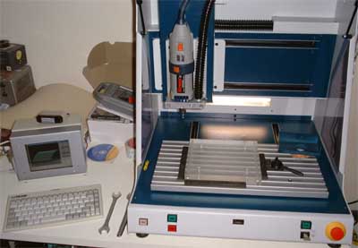 Upon special request here a picture of
my CNC mill is added. It is an isel CPM 3020 <http://www.isel.de> , initially bought for making front panels and PCBs for prototype electronic equipment. It proved to be useful for many other things, though. Currently it
is capable of three dimensions, while the controller inside will power a fourth actuator. So I will probably add a rotational axle soon. The motion range of the three axles is 300x200x120mm³. One of the
goodies is that the cabinet can be closed and a vacuum cleaner connected as to extract the dust. The small PC on the left is an industrial slot-CPU 486 (super-sophisticated high performance, latest
model 10GHz... ;-) equipped with a 6 TFT display. The speed of this PC is of no concern at all as it will be faster than the mechanical components of the mill in any case. It is equipped with a
networking adapter to upload the vector data from the CAM system on my workstation.
Upon special request here a picture of
my CNC mill is added. It is an isel CPM 3020 <http://www.isel.de> , initially bought for making front panels and PCBs for prototype electronic equipment. It proved to be useful for many other things, though. Currently it
is capable of three dimensions, while the controller inside will power a fourth actuator. So I will probably add a rotational axle soon. The motion range of the three axles is 300x200x120mm³. One of the
goodies is that the cabinet can be closed and a vacuum cleaner connected as to extract the dust. The small PC on the left is an industrial slot-CPU 486 (super-sophisticated high performance, latest
model 10GHz... ;-) equipped with a 6 TFT display. The speed of this PC is of no concern at all as it will be faster than the mechanical components of the mill in any case. It is equipped with a
networking adapter to upload the vector data from the CAM system on my workstation.
-----------------------------------------------------------------------------------------------------------------------------------
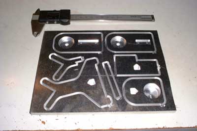 This is what the plate looked like after
about three hours of milling (oh yeah, my landlady LOVES it ;-). All contour cuts and pockets are 10mm in depth except the receptacles for the piezo transducers, which are stepped as to provide a proper seat for the
transducers. When I mill multiple parts out of a single plate I usually set the cutting depth so as to leave approx. 50µm of material at the bottom intact to prevent the finished parts from
falling out. They can easily be cut out with a sharp knife afterwards.
This is what the plate looked like after
about three hours of milling (oh yeah, my landlady LOVES it ;-). All contour cuts and pockets are 10mm in depth except the receptacles for the piezo transducers, which are stepped as to provide a proper seat for the
transducers. When I mill multiple parts out of a single plate I usually set the cutting depth so as to leave approx. 50µm of material at the bottom intact to prevent the finished parts from
falling out. They can easily be cut out with a sharp knife afterwards.
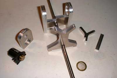 And here are the parts ready for
further machining. They are cut out and cleaned and then set together so you get an idea how the device will look when finished. All the different plates will be clamped to a steel shaft
to ensure rigidity. The front Y part is the fixed bearig, the Y sitting on the right will be connected with a spring type brass sheet to the center of the second part sitting on the shaft. This
brass sheet will allow slight radial movement of this bearing while still providing rigidity in axial direction. This small movement will be transferred by a connecting rod (not
yet displayed) to two piezo transducers, forming a push-pull arrangement. One of the transducers can be seen in the foreground. The balancing shaft will be driven by a small electric motor (on the
left) via a belt. This particular motor was salvaged from an old VCR. I checked about 20 motors from my collection until I found this one which was running sufficiently smooth.
And here are the parts ready for
further machining. They are cut out and cleaned and then set together so you get an idea how the device will look when finished. All the different plates will be clamped to a steel shaft
to ensure rigidity. The front Y part is the fixed bearig, the Y sitting on the right will be connected with a spring type brass sheet to the center of the second part sitting on the shaft. This
brass sheet will allow slight radial movement of this bearing while still providing rigidity in axial direction. This small movement will be transferred by a connecting rod (not
yet displayed) to two piezo transducers, forming a push-pull arrangement. One of the transducers can be seen in the foreground. The balancing shaft will be driven by a small electric motor (on the
left) via a belt. This particular motor was salvaged from an old VCR. I checked about 20 motors from my collection until I found this one which was running sufficiently smooth.
The bearings will be formed by cylindrical PTFE pieces of 6mm diameter that will have to be inserted into the inner side of the arms of the Y shaped bearing parts. This way it is possible to avoid ball bearings that will always induce a small amount of imbalance, and allow balancing of rotors with different shaft diameters without having to modify the setup. Once the mechanical components are finished I will design the electronics. If somebody is interested in details I might convert the drawings from my CAD/CAM system to DXF and publish them to this site (the information in these is rather limited though, because most of the design I did in crude free-hand sketches).
Added 12/19/2000
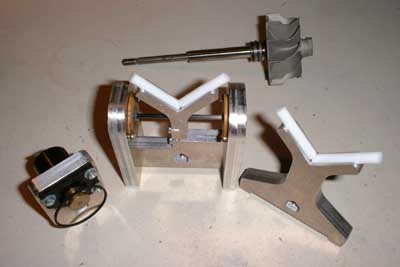 Today I completed the mechanical
work on the balancer. Unfortunately I wrecked both piezoelectric transducers while matching the length of the connecting rod. They are inexpensive, but Ill have to order them and thus progress will be delayed a
little. The PTFE bearing sticks arent yet fixed to the bearing supports, they are just sitting in the slots milled into the inner sides of the Y legs. Kerosene works great for lubricating them! Some experiments revealed
that the electric motor might be a little weak for this purpose, but I still can try a smaller belt pulley.
Today I completed the mechanical
work on the balancer. Unfortunately I wrecked both piezoelectric transducers while matching the length of the connecting rod. They are inexpensive, but Ill have to order them and thus progress will be delayed a
little. The PTFE bearing sticks arent yet fixed to the bearing supports, they are just sitting in the slots milled into the inner sides of the Y legs. Kerosene works great for lubricating them! Some experiments revealed
that the electric motor might be a little weak for this purpose, but I still can try a smaller belt pulley.
Added 12/29/2000
 Finally I got the spare piezoelectric
transducers and finished some simple high-impedance signal amplifiers. On the Scope the imbalance signal can clearly be observed, the setup is increadibly sensitive. Yet I have to build some kind of trigger circuit to
flash a LED in order to find the heavy side of the item to be balanced. This will also contain all the power supplies (for motor and amplifiers). On this particular turbocharger turbine wheel I
used the inner races of two ball bearings to prevent the shaft from moving axially. Despite of this the quality of the surface of these races is very good, thus generating low noise that would effect a nasty hiss
superimposed to the signal.
Finally I got the spare piezoelectric
transducers and finished some simple high-impedance signal amplifiers. On the Scope the imbalance signal can clearly be observed, the setup is increadibly sensitive. Yet I have to build some kind of trigger circuit to
flash a LED in order to find the heavy side of the item to be balanced. This will also contain all the power supplies (for motor and amplifiers). On this particular turbocharger turbine wheel I
used the inner races of two ball bearings to prevent the shaft from moving axially. Despite of this the quality of the surface of these races is very good, thus generating low noise that would effect a nasty hiss
superimposed to the signal.
Added 01/12/2001
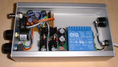
Well, at least the electronic components for the trigger circuit made it. So no cabinet for the electronics yet - bad luck. And this is what the balancer currently looks like:
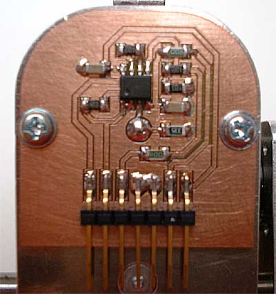
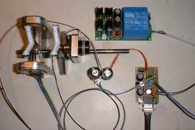 On top with the blue transformer sits
the power supply. I had some PCBs left from a design I did earlier for a scientific research project, so I used one of the power boards to build a symmetric power supply (+8 and - 8Volts). The small PCB in the lower
right contains the Trigger/LED flasher circuit as well as a simple PWM motor controller. The two variable resistors in the center are for controlling motor speed and trigger level. The rest are
mostly wires ;-). I use an ultrabright white LED, and this is really unbelievably bright. The circuit worked more or less immediately, I just had to
change the timing capacitor for the PWM to a smaller value. The trigger circuit sensitivity well matches my expectations, it recognizes easily if one shouts at the balancer ;-). It also turned out to
be a good choice to spend some money for a ten-turn variable resistor for adjusting the trigger. I will soon do some rectifications to the schematics and then publish them to this page.
On top with the blue transformer sits
the power supply. I had some PCBs left from a design I did earlier for a scientific research project, so I used one of the power boards to build a symmetric power supply (+8 and - 8Volts). The small PCB in the lower
right contains the Trigger/LED flasher circuit as well as a simple PWM motor controller. The two variable resistors in the center are for controlling motor speed and trigger level. The rest are
mostly wires ;-). I use an ultrabright white LED, and this is really unbelievably bright. The circuit worked more or less immediately, I just had to
change the timing capacitor for the PWM to a smaller value. The trigger circuit sensitivity well matches my expectations, it recognizes easily if one shouts at the balancer ;-). It also turned out to
be a good choice to spend some money for a ten-turn variable resistor for adjusting the trigger. I will soon do some rectifications to the schematics and then publish them to this page.
Added 01/14/2001
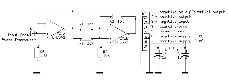
Finally I extracted both the schematics of the high-impedance buffers and the trigger circuit from my electronics CAD system and converted them into jpegs. These are probably a little small (as server space is a concern), but readable. Both circuits are tested to work properly. Just click on the captions below to display (or download) them.
 Since my balancing setup
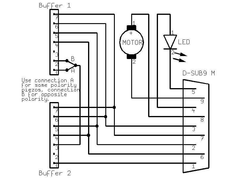
incorporates two piezo transducers in push-pull configuration, I built two of the buffers, and so the signals from both transducers will have to be subtracted from each other. But as I discovered, the piezo disk in the
transducers is not necessarily polarized in the same direction on each, an addition of the signal must also be possible. This is done by connecting the corresponding output of the first buffer to the inverting input
of the second. Either the "negative or differential" (for opposite polarity transducers) or the "positive" (for same polarity transducers) output of the first buffer is routed to the
"negative input" of the second buffer. Imbalance signal is measured at the "negative or differential output" of the second buffer. All other inputs/outputs are left open, the ground and power
supply pins are connected in parallel. For simplicity I added a schematic of this (01/31/2001), klick below.
Since my balancing setup
incorporates two piezo transducers in push-pull configuration, I built two of the buffers, and so the signals from both transducers will have to be subtracted from each other. But as I discovered, the piezo disk in the
transducers is not necessarily polarized in the same direction on each, an addition of the signal must also be possible. This is done by connecting the corresponding output of the first buffer to the inverting input
of the second. Either the "negative or differential" (for opposite polarity transducers) or the "positive" (for same polarity transducers) output of the first buffer is routed to the
"negative input" of the second buffer. Imbalance signal is measured at the "negative or differential output" of the second buffer. All other inputs/outputs are left open, the ground and power
supply pins are connected in parallel. For simplicity I added a schematic of this (01/31/2001), klick below.
Interconnection diagramm (49k)
The nomenclature of the inputs/outputs is strictly speaking not exactly correct, but it serves its purpose ;-)
The transducers are just piezo buzzers (27mm brass sheet disk with piezo-ceramic material bonded to one face), and in Europe they are available through Conrad Electronic <http://www.conrad.com> (order No. 712-930).
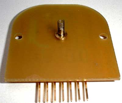 I connected the piezo disks by a small
spring, as displayed in this picture.
I connected the piezo disks by a small
spring, as displayed in this picture.
The ground return of the piezo discs is accomplished through the structural parts of the balancer.
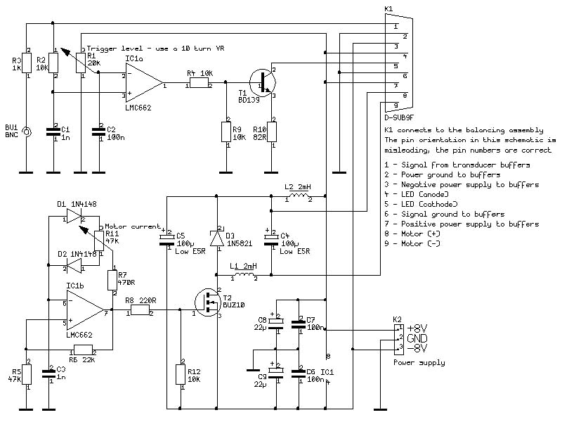
The trigger PCB consists of two parts, first (upper half of the schematic) the trigger and constant-current LED drive and second (lower half) the PWM motor current controller. Both circuits are straight-ahead designs, and if the motor controller isnt required, it simply can be left away. The BNC jack can be connected to a scope or a true-RMS AC voltmeter to measure the degree of imbalance. It is very important when doing measurements with this setup that it is seated firmly to avoid resonances. If they nevertheless occur, a rotational speed should be selected that is way off the resonance frequencies.
The Motor current controller can be loaded with up to 1A, depending on the inductors. Usually the motors for turning the part to be balanced wont need to be very powerful, so this current should be more than enough. The Motor RPM isnt stabilized, so it needs to be adjusted properly by hand.
Added 01/14/2001
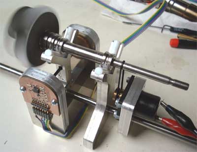
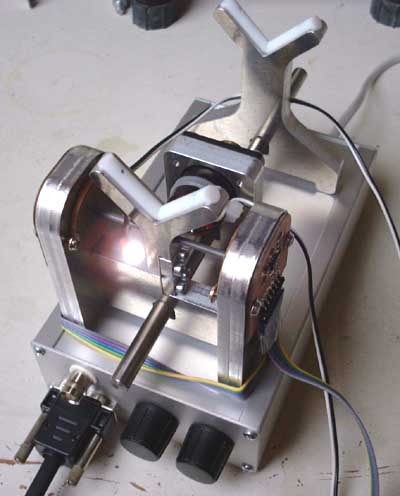
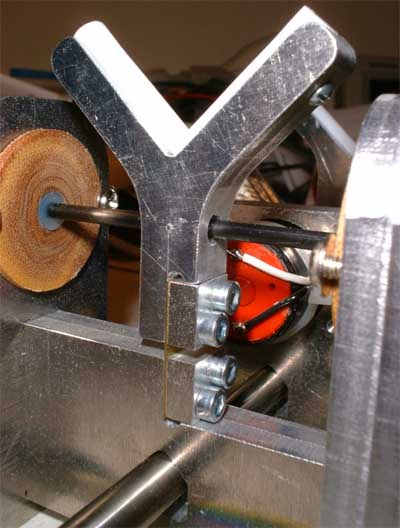 Upon special request I added this
close-up of the transducer assembly. The moving Y has a 5 mm hole drilled through it, through which runs the carbon fibre reinforced epoxy connecting rod. It is cross-drilled and fixed with a 0.8mm steel needle. The
ugly-looking piezo disk retainers are made from plastic (in this case reinforced phenolic resin, I just had no other material handy, looks and smells like s**t ;-). The spring brass sheet accepts the axial and gravitational
forces, but allows radial movement in one dimesion. The steel rod that connects the different shaft supports and the motor mounting plate is clamped with a small screw (M3).
Upon special request I added this
close-up of the transducer assembly. The moving Y has a 5 mm hole drilled through it, through which runs the carbon fibre reinforced epoxy connecting rod. It is cross-drilled and fixed with a 0.8mm steel needle. The
ugly-looking piezo disk retainers are made from plastic (in this case reinforced phenolic resin, I just had no other material handy, looks and smells like s**t ;-). The spring brass sheet accepts the axial and gravitational
forces, but allows radial movement in one dimesion. The steel rod that connects the different shaft supports and the motor mounting plate is clamped with a small screw (M3).
Finished 01/29/2001
Today I got the missing cabinet for the electronics. After CNC milling the openings for the variable resistors and the jacks I assembled the components.
 Theres still some space left in the
cabinet, but I cannot imagine whats missing ;-).
Theres still some space left in the
cabinet, but I cannot imagine whats missing ;-).
The mains switch is located on the rear cover along with the AC inlet, all the other knobs and jacks are on the front.
 This is a view of the finished balancer.
Well, perhaps Ill add some covers for the buffer PCBs later, but for now Im absolutely satisfied with the result. The white spot is the LED so you get an idea how bright it is. I already did
some balancing with the trigger / LED assembly and the result is almost perfect. I used textile adhesive tape as counterweight, and the balancer will detect a piece of about 2mm² area. I guess the balancing result,
once I have acquired some experience with this device, can be better than 1mg*cm. This accuracy isnt limited by the sensitivity of the pickup system, but by the quality of the shaft surface and the noise generated
by the rotation. Maybe even the vanes of the wheels will produce enough eddies in the air to affect the result when balancing in the low milligramm regions.
This is a view of the finished balancer.
Well, perhaps Ill add some covers for the buffer PCBs later, but for now Im absolutely satisfied with the result. The white spot is the LED so you get an idea how bright it is. I already did
some balancing with the trigger / LED assembly and the result is almost perfect. I used textile adhesive tape as counterweight, and the balancer will detect a piece of about 2mm² area. I guess the balancing result,
once I have acquired some experience with this device, can be better than 1mg*cm. This accuracy isnt limited by the sensitivity of the pickup system, but by the quality of the shaft surface and the noise generated
by the rotation. Maybe even the vanes of the wheels will produce enough eddies in the air to affect the result when balancing in the low milligramm regions.
Another good news is that an oscilloscope is definitely not
necessary as the ten-turn trigger preset will be just fine for estimating the quantity of imbalance and evaluating the condition of least imbalance. In some details the device might still be simplified.
Added 03/19/2001
A new page containing information about available electronics parts and assembly instructions has been added.