Garrett VNT15 repair pictures
Recently I got the chance to obtain a Garrett VNT15 variable turbine geometry turbocharger rather cheap. This turbo is mainly used in the new VW/Audi TDI engines up to 110bhp. I intend to build an experimental gas turbine engine from this turbo, but Ill carry out only modifications on it that are reversible. This is because I can also use this turbo as a spare for my cars engine (Audi A3 TDI), and if I should ever be in the situation to need it, Ill be happy to have a spare handy, because the original replacement would be quite expensive.
At the time of purchase I didnt know the reason of the turbo removement, but I blamed this to a bad accident with damage to the engine beyond repair. I was
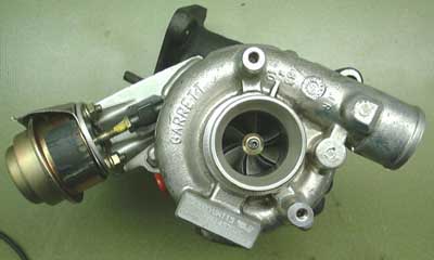
told the turbo ran well at the time of removal and the car was manufactured 1997 with now about 40.000km on it. And this is what it looked like as I got it: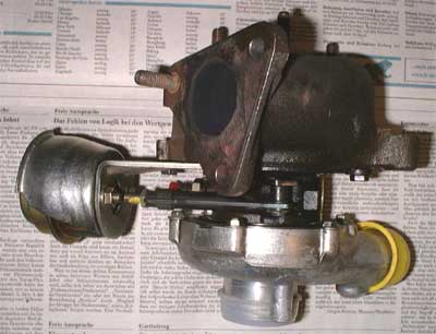
I was really astonished that it was this clean on the outside and revealed only minor corrosion.
The can on the left is the vacuum actuator for the NGV controlling gear. This turbo is a rather small unit, weight just about 5kg. Look how shiny the compressor housing still is.
I noticed, though, that the NGV actuating mechanism was rather stiff, if not to say stuck (at this time yet I didnt know why).
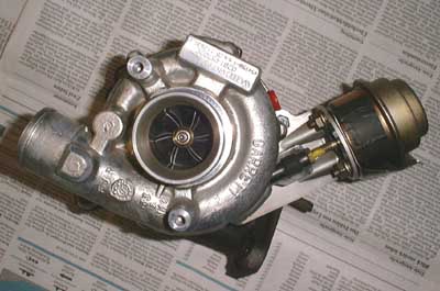 A view into the intake. This side is
also quite clean, the compressor wheel except a very thin layer of dirt in mint condition.
A view into the intake. This side is
also quite clean, the compressor wheel except a very thin layer of dirt in mint condition.
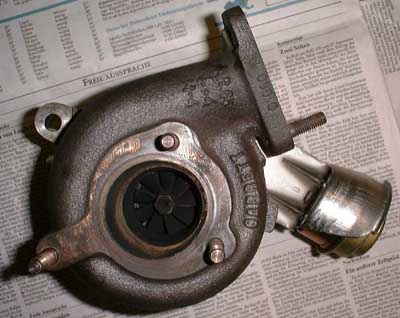 The exhaust section and the turbine
wheel are very sooty. I dont know if this can be considered as normal on this type of engine because the car exhausts almost no smoke at all, even if driven hard.
The exhaust section and the turbine
wheel are very sooty. I dont know if this can be considered as normal on this type of engine because the car exhausts almost no smoke at all, even if driven hard.
 Oops, I did it again!
(Though I definitely must say that Im no fan of Britney Spears music)
Well, I once promised myself I would never ever again take a turbocharger apart, since the last time I did it I had to live with traces of black underneath my fingernails for about one week. But this one looks so much cleaner, that I forgot about this promise.
The compressor came apart like this, almost no cleaning required!
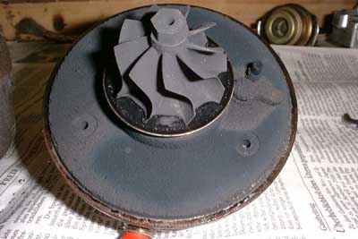 Unfortunately I was glad about the
ceanliness of the turbo too soon - this is a view of the turbine, a layer of soot of approx. 1mm all over it.The lever in the 3 oclock position is part of the NGV actuating system.
Unfortunately I was glad about the
ceanliness of the turbo too soon - this is a view of the turbine, a layer of soot of approx. 1mm all over it.The lever in the 3 oclock position is part of the NGV actuating system.
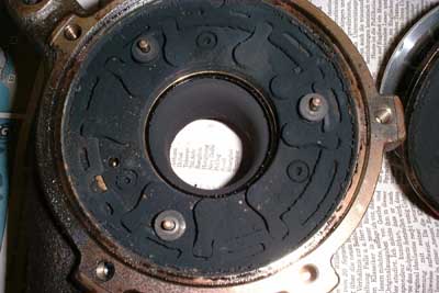 This is what the NGV actuating gear
looked like after disassembly. Did I say something about clean before ??!! ;-)
This is what the NGV actuating gear
looked like after disassembly. Did I say something about clean before ??!! ;-)
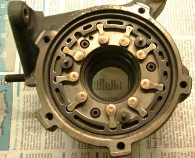 And this is what it looks like some
really dirty hands later...
And this is what it looks like some
really dirty hands later...
Each of the nine levers is welded to the shaft of the corresponding nozzle guide vane (NGV). The control ring is moved by the main lever, located in the turbos bearing housing, projecting into the free notch in the 11 oclock position.
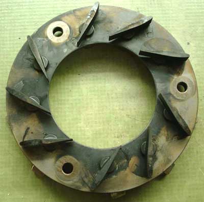 And this is the other side of the NGV
system (removed from the turbine housing and cleaned). Notice the cute airfoil shape of the vanes. This is the maximum exhaust flow - minimum charge pressure - position.
And this is the other side of the NGV
system (removed from the turbine housing and cleaned). Notice the cute airfoil shape of the vanes. This is the maximum exhaust flow - minimum charge pressure - position.
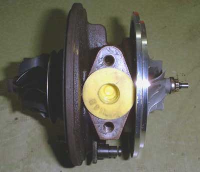
 The turbine wheel and bearing
housing cleaned (I dont think Ill get this dirt off my hands ever again). The NGV actuating main lever can also be seen.
The turbine wheel and bearing
housing cleaned (I dont think Ill get this dirt off my hands ever again). The NGV actuating main lever can also be seen.
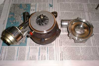
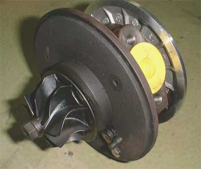
 The turbo core. I didnt take the rotor
apart because the bearings seem to be in a pretty good condition and I dont want to tamper with the rotor blancing (this one spins in excess of 200krpm). Just below the oil return the outer NGV actuating lever is visible.
The turbo core. I didnt take the rotor
apart because the bearings seem to be in a pretty good condition and I dont want to tamper with the rotor blancing (this one spins in excess of 200krpm). Just below the oil return the outer NGV actuating lever is visible.
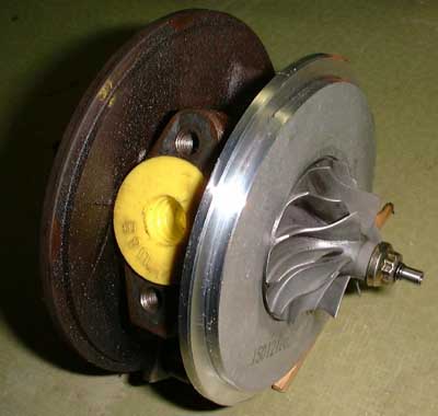 The compressor side of the turbo
core. The wheel is finally cleaned, too. This wheel is 44mm in diameter (turbine 43mm), so you get a clue how small the whole unit is. I was rather relieved to find that Garrett finally decided to use a left-hand thread for
joining the rotor components together.
The compressor side of the turbo
core. The wheel is finally cleaned, too. This wheel is 44mm in diameter (turbine 43mm), so you get a clue how small the whole unit is. I was rather relieved to find that Garrett finally decided to use a left-hand thread for
joining the rotor components together.
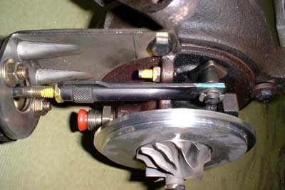 Thats the adjustable connecting rod
from the NGV vacuum actuator to the outer main lever. This allows to adjust the sensitivity of the whole mechanism. An adjustable throw limiting screw is located just above the center of the connecting rod.
Thats the adjustable connecting rod
from the NGV vacuum actuator to the outer main lever. This allows to adjust the sensitivity of the whole mechanism. An adjustable throw limiting screw is located just above the center of the connecting rod.
The mechanism works this way that an increasing vacuum (decrease of absolute control pressure) effects an increasing charge air pressure. Thus this system is fail-safe, should a tube break, the turbo will supply minimum charge pressure.
 And thats the last picture (yet) (thanks
for your patience). Now that the turbos cleaned and reassembled the NGV actuating gear works much smoother.
And thats the last picture (yet) (thanks
for your patience). Now that the turbos cleaned and reassembled the NGV actuating gear works much smoother.
Yet the turbo waits for some very bad mistreatment: Ill probably design a small combustion chamber and try if
the VTG system is beneficial for converting it into an experimental gas turbine engine and if possibly some shaft power could be extracted. So stay tuned for further development (though it will still take a while, too
many projects at a time...).
Added 11/26/2000:
 Upon special request I added this
sequence of the moving NGV system. The file is large, so please be patient while loading.
Upon special request I added this
sequence of the moving NGV system. The file is large, so please be patient while loading.