Russian APU TS-21
 New acquisition! Once again I had
some luck and obtained a surplus small turbine engine for comparably little money. This one is a Russian Starter/APU engine with most uncommon design features. Yet I wasnt able to identify the
manufacturer, his logo looks like a turbine wheel with symbolic wings to both sides. The type of the engine is TC-21, but as this is written in cyrillic letters it might as well be TS-21. At
least under this designation I found a web entry of a Polish turbine and APU repair shop.
New acquisition! Once again I had
some luck and obtained a surplus small turbine engine for comparably little money. This one is a Russian Starter/APU engine with most uncommon design features. Yet I wasnt able to identify the
manufacturer, his logo looks like a turbine wheel with symbolic wings to both sides. The type of the engine is TC-21, but as this is written in cyrillic letters it might as well be TS-21. At
least under this designation I found a web entry of a Polish turbine and APU repair shop.
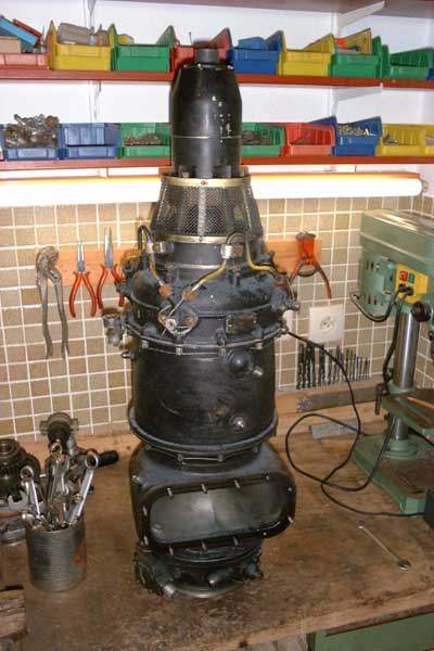
I guess this engine will replace my Solent unit as my most powerful turbine. I had been told this beast is capable of 200hp maximum power but unfortunately I havent got any exact information (please see update at the bottom of this page). The size of this engine is about 80cm long and 25cm diameter, it weighs approx 40kg (guessed).
This engine is a twin shaft unit (free power turbine) of a very interesting design. The starter motor is mounted axially in front of the compressor and adds quite some to the the total length of the unit. Starter torque is transferred by a bendix type clutch. Once this clutch has disengaged, the gas generator rotor spins totally free. There arent any gears or accessories coupled to its shaft. This will probably grant a very low self-sustain speed. The compressor is of a semi-diagonal design and the air exiting the compressor wheel is guided directly in an axial direction. Here a completely axial diffuser stage is located. This allows a rather slim engine with a 180mm diameter compressor wheel. If the omitted radial diffuser stage causes a siginificant loss in efficiency or pressure ratio still needs to be figured out. Now the air enters the combustor section which is of straight flow-through design with four simplex burners. The annular flame tube has four domes at the front where swirl is generated and fuel is injected. The hot combustion products consequently flow through an axial NGV and then through the first turbine stage which drives the compressor. These first stage turbine blades have an almost unbelievable shallow exit angle which causes the exiting gas to strongly rotate in the opposite direction of this wheel. This way theres no need for an NGV for the second stage turbine (free power turbine), this stage is simply constructed to be counterrotating to the first one. Some of the compressor air is bled off to cool the exhaust duct, the gearbox housing and the rear face of the power turbine disk. Both turbine rotors (diameters of 160 and 167mm) are constructed as disks with fir-tree slots to attach the blades, a quite uncommon technique for such small turbines that usually incorporate blisks, i.e. the turbine disks are cast in one piece with all the blades.
The engine has accumulated a lot of dirt during storage, it seems it has been immersed in oil (possibly for conservation?), so any dust sticks very well to it. Yet it is not that difficult to clean the components, so this is what Im doing currently. Some pictures taken during the diassembly follow.
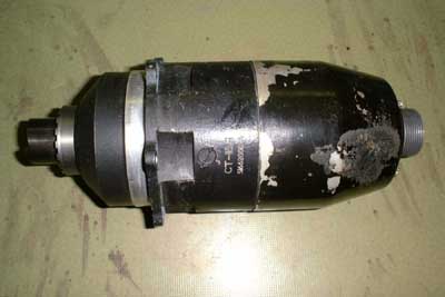 The starter motor with the bendix
clutch on the left and the electrical connector on the right side. I have no idea of its electrical characteristics but most probably it will be rated at 28V.
The starter motor with the bendix
clutch on the left and the electrical connector on the right side. I have no idea of its electrical characteristics but most probably it will be rated at 28V.
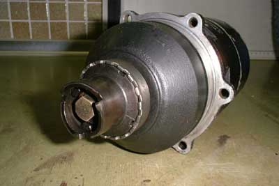 A view onto the bendix clutch. This will
allow the gas generator rotor to spin freely without any friction when gas generator speed surpasses the starter motor speed.
A view onto the bendix clutch. This will
allow the gas generator rotor to spin freely without any friction when gas generator speed surpasses the starter motor speed.
 This is the intake of the turbine. The
flange partially visible in the upper area of the picture accepts the debris guard and the starter motor.
This is the intake of the turbine. The
flange partially visible in the upper area of the picture accepts the debris guard and the starter motor.
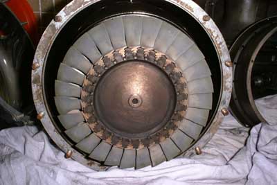
 This is a shot up the exhaust flange.
The free power turbine wheel is visible. Unfortunately three of the flange bolts are broken so I must find a way to remove the stubs and re-tap the threads. This kind of flange makes designing a proprietary exhaust pipe
very simple. The whole exhaust duct is a hollow double-walled structure. The space between both walls is flooded with compressor bleed air to allow as little heat as possible to be transferred to the gear box.
This is a shot up the exhaust flange.
The free power turbine wheel is visible. Unfortunately three of the flange bolts are broken so I must find a way to remove the stubs and re-tap the threads. This kind of flange makes designing a proprietary exhaust pipe
very simple. The whole exhaust duct is a hollow double-walled structure. The space between both walls is flooded with compressor bleed air to allow as little heat as possible to be transferred to the gear box.
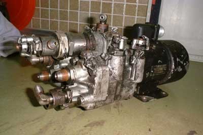 This is the complete fuel system of the
engine. A single electric motor drives both fuel and oil pumps. Integral part of this assembly is a fuel/acceleration control unit. This unit is operated pneumatically so that no mechanical links (except pipes and hoses) are
required between the engine and its supplementary systems.
This is the complete fuel system of the
engine. A single electric motor drives both fuel and oil pumps. Integral part of this assembly is a fuel/acceleration control unit. This unit is operated pneumatically so that no mechanical links (except pipes and hoses) are
required between the engine and its supplementary systems.
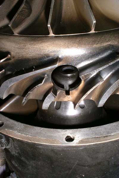
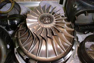 This is the semi-diagonal compressor
wheel. inside the hub the second member of the bendix clutch is visible. The wheel seems to be made up of two separate parts but I dont know if the inducer vanes section can actually be separated from diagonal impeller
section (or if its a good idea to try it ;-).
This is the semi-diagonal compressor
wheel. inside the hub the second member of the bendix clutch is visible. The wheel seems to be made up of two separate parts but I dont know if the inducer vanes section can actually be separated from diagonal impeller
section (or if its a good idea to try it ;-).
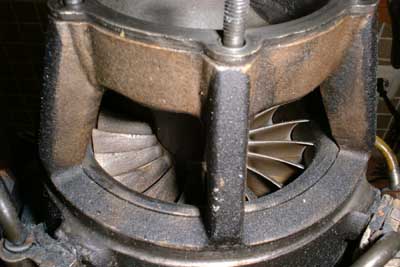
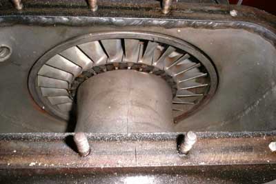
 Heres a side view of the compressor,
notice that there are only axial diffuser vanes. Just below the diffuser two of the four swirl domes of the combustor are visible.
Heres a side view of the compressor,
notice that there are only axial diffuser vanes. Just below the diffuser two of the four swirl domes of the combustor are visible.
 Thats the inside of the compressor
cover. The area the compressor wheel is rotating is covered with some kind of polymer coating that can be machined away in case the compressor wheel comes into contact with the cover. What purpose the ring
of bores at the transition area between inducer vanes/diagonal impeller section of the compressor wheel serves, I dont know. There doesnt seem to be any access to this confined space from the outside of the
compressor housing. Maybe this is some kind of compressor muffler, but who actually knows? ;-)
Thats the inside of the compressor
cover. The area the compressor wheel is rotating is covered with some kind of polymer coating that can be machined away in case the compressor wheel comes into contact with the cover. What purpose the ring
of bores at the transition area between inducer vanes/diagonal impeller section of the compressor wheel serves, I dont know. There doesnt seem to be any access to this confined space from the outside of the
compressor housing. Maybe this is some kind of compressor muffler, but who actually knows? ;-)
 This picture shows one of the orifices
through which the fuel nozzles project and reach just on top of the burner dome.
This picture shows one of the orifices
through which the fuel nozzles project and reach just on top of the burner dome.
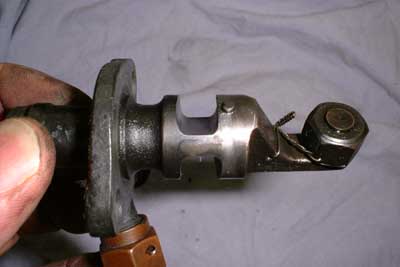 And this is one of the burner nozzles
along with some dirty fingers ;-).
And this is one of the burner nozzles
along with some dirty fingers ;-).
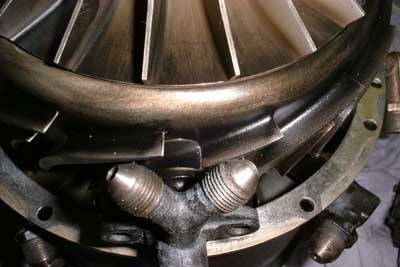 Here you can see how well the
profiled shaft of the injection nozzles matches the cut-out part of the diffuser channel. A really cute design detail.
Here you can see how well the
profiled shaft of the injection nozzles matches the cut-out part of the diffuser channel. A really cute design detail.
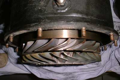 Thats a view on part of the gas
generator NGV and the turbine wheel. Ive never seen before any turbine blades that perform such a strong transition from impulse to reaction profile. Also notice the shallow exit angle of the turbine blades.
Thats a view on part of the gas
generator NGV and the turbine wheel. Ive never seen before any turbine blades that perform such a strong transition from impulse to reaction profile. Also notice the shallow exit angle of the turbine blades.
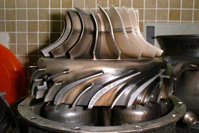
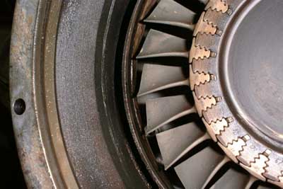
 This photo is taken from the rear of
the gas generator turbine wheel. Look at these beautiful fir tree roots of the blades. I always thought for small turbines as this one this would be way too expensive
This photo is taken from the rear of
the gas generator turbine wheel. Look at these beautiful fir tree roots of the blades. I always thought for small turbines as this one this would be way too expensive
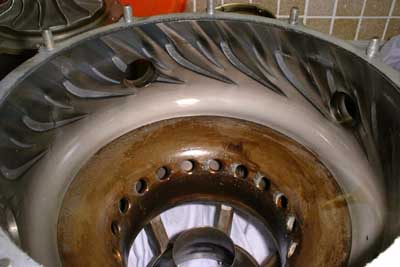
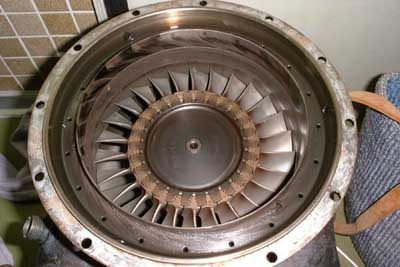 Thats the tree power turbine wheel
inside of the shroud for both turbine stages. Notice the many small bores on the circuference of the shroud. These meter the compressor bleed air to the cooling cavity of the exhaust duct.
Thats the tree power turbine wheel
inside of the shroud for both turbine stages. Notice the many small bores on the circuference of the shroud. These meter the compressor bleed air to the cooling cavity of the exhaust duct.
 Another view of the free power
turbine, this time with the turbine shroud removed. The passage between the ring next to the turbine blades and the sooty outer component is the entry to the cooling cavity. The air enters there and exits through a
recess of the inner exhaust duct lining that directs the cooling air to the rear of the free power turbine disk. Another nice view of the fir tree turbine blade roots. Each blade and each slot have
a matching number engraved to get the blades into the right slots after inspections.
Another view of the free power
turbine, this time with the turbine shroud removed. The passage between the ring next to the turbine blades and the sooty outer component is the entry to the cooling cavity. The air enters there and exits through a
recess of the inner exhaust duct lining that directs the cooling air to the rear of the free power turbine disk. Another nice view of the fir tree turbine blade roots. Each blade and each slot have
a matching number engraved to get the blades into the right slots after inspections.
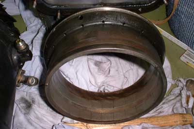 This is the turbine shroud as seen
from the free power turbine side. Once again the cooling air metering bores are visible.
This is the turbine shroud as seen
from the free power turbine side. Once again the cooling air metering bores are visible.
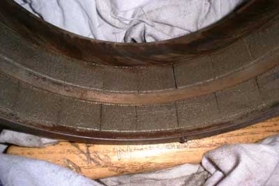 This is a closeup photo of the inside
of the turbine shroud. There seem to be ceramic (or carbon??) pads inserted in the places where the turbine blades rotate.Without heat and rotation the blade tip clearance to these pads is about 0.5mm but I
wonder if this lining is designed to be machined away by the turbine blades should they eventually come into contact with it. Yet there are no traces of wear to these components.
This is a closeup photo of the inside
of the turbine shroud. There seem to be ceramic (or carbon??) pads inserted in the places where the turbine blades rotate.Without heat and rotation the blade tip clearance to these pads is about 0.5mm but I
wonder if this lining is designed to be machined away by the turbine blades should they eventually come into contact with it. Yet there are no traces of wear to these components.
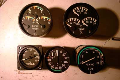
All in all this engine seems to be in a very good condition, some minor repairs need to be done but nothing really difficult. After cleaning of all the components Ill need to draw up a basic schematic of this engine to find out where all the pipes from the fuel controller need to be attached. Maybe I could also add some basic instrumentation, some nice turbine instruments Ive got already :-)
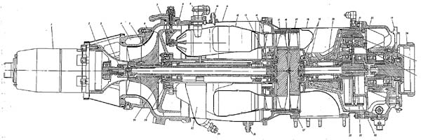
Update 05/05/2002: I finally got the manual (in Russian, but better than nothing at all). Referring to this, the engine is significantly less powerful that I had been told before. The manual conatains a torque vs. rpm curve. This reveals a maximum power of 63kW at 2400rpm output shaft speed. Here are some schematics of the engine, please click the pictures for VERY large TIFF versions.
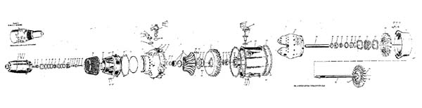
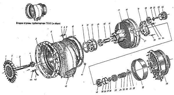
If somebody is interested in a copy of this manual, Ill be able to provide a simple PDF version of it on CDR. The quality is a little poor, but I think the important parts are readable. I would be very happy if someone who speaks Russian would be willing to help me translating parts of the manual into English or German. This job wont need to be for free, but I dont want to pay professional translators fees either. Maybe it could also be part of a trade...
Gearbox disassembly - click here!
Fuel control details - click here!
A damaged ignition exciter had to reveal its secrets as well.